
- esp32c3.png (32.59 KiB) Viewed 8781 times
enable a device from rules
Moderators: grovkillen, Stuntteam, TD-er
enable a device from rules
is there is a way to enable a device from a Rules ? Thank you !

Re: enable a device from rules
Here is an example of the command to do it for Task 1. It needs to be added to a rule set, such as System#Boot. Or a timer. Or where ever it makes sense for your application.
I know TaskEnable works because I have used it many times.
But the reason your tasks 1 & 2 are being disabled is because they are both using I2C address 0x29. ESPEasy will recognize this mistake (plugins will fail) and automatically disable them.
You must reconfigure one of them to another I2C address. Or use an I2C expander.
- Thomas
Code: Select all
 if [TOF200C#settings.enabled]=0 // Plugin Disabled
   TaskEnable TOF200C // Enable Task
 endif
But the reason your tasks 1 & 2 are being disabled is because they are both using I2C address 0x29. ESPEasy will recognize this mistake (plugins will fail) and automatically disable them.
You must reconfigure one of them to another I2C address. Or use an I2C expander.
- Thomas
Re: enable a device from rules
Also if switching between sensors using taskenable/disable was a deliberate attempt, then both sensors will reply if you address something on the I2C bus at that address.
The plugins for VL53L0X and VL53L1X are not interchangable to use the same sensor with different settings.
One more thing to keep in mind: The state change done by taskdisable/taskenable is only done in memory.
So after a reboot, the saved state will be active.
If you save something (also if it is just pressing 'submit' on another task), the current enabled/disabled state in memory will also be saved.
Re: enable a device from rules
Thank you so much for your reply ThomasB and TD-er, this was exactly what I was searching for, I tested it and it work as expected. Now that I know what to search in the doc, I see it. Still it is not obvious to me but probably because I'm new to rules, tasks and devices.
I should had remove the TOF200C from my screenshot, it only add to confusion. It was from prior test but now I decided to use TOF400C and only enable that device. I left TOF200C disabled there in case I wanted to test it quickly, but maybe it's a bad idea. Since my design is still in development, the ESPEasy firmware tend to disable the sensor quite often. I noticed it would do it when I enable the device in it's device configuration, if it's not detected it would automatically disable it and also in the boot as part of some protection. When it does so, does it save configuration that the device is disabled or just momentarily disable it until next reboot ? According to TD-er post here, it seem both case must be when PLUGIN_INIT is called. It seem to me I could not observe any difference in the behavior when "Check I2C devices when enabled" is checked or not.
I have set the ToF device to constantly send information and with a dummy device called watchdog that monitor if it has received any information. Every 30 seconds the timer monitor if the ToF sent anything and if not then it reboot the ESP32C3, hoping that will re-initiate communication. Now that I start to have a better understanding of it all I have to review my script and I have an idea to make the wiring more reliable, but in the meantime here the Rules so far.
Code: Select all
On System#Boot do
 GPIO,3,0 //reset led
 GPIO,4,1
 if [TOF400C#settings.enabled]=0 // Plugin Disabled
  TaskEnable TOF400C // Enable Task
 endif
 timerSet,1,30 // setup watchdog
 TaskValueSet 3,1,0 // reset challenge
Endon

On TOF400C#All do
TaskValueSet 3,1,1 // sensor is alive, fulfill challenge
  If [TOF400C#Distance]>350
  GPIO,3,1 // something is detected swap lights
  GPIO,4,0
 Else
  GPIO,3,0
  GPIO,4,1
 Endif
Endon

On Rules#Timer=1 do //watchdog timer, have we received anything ?
 timerSet,1,30 // setup next timer
 If [WATCHDOG#Dummy]=1 // yes we received something :)
  TaskValueSet 3,1,0 // sensor is alive, reset it's watchdog challenge
 Else
  Reboot //sensor sent nothing, reboot device
 Endif
endon
Re: enable a device from rules
There is typically no need to reboot if the TOF sensor is disabled. You can simply perform the TaskEnable instead.
And I think you can eliminate the dummy challenge var and instead replace your timer #1 code with this:
I am using the VL53L01 in a project with great success. The i2c cable is 100cm long. I needed to add 1.5Kohm pullups to the existing 10K pull-ups. The new pullups are installed near the ESP32. In my configuration it does not experience task disable problems.
- Thomas
And I think you can eliminate the dummy challenge var and instead replace your timer #1 code with this:
Code: Select all
On Rules#Timer=1 do //watchdog timer
 if [TOF400C#settings.enabled]=0 // TOF task Disabled!
  TaskEnable TOF400C // Enable Task
  timerSet,1,5 // Reload short watchdog timer. Check back sooner in case it did not enable.
 else
  timerSet,1,30 // Reload long watchdog timer
 endif
endon- Thomas
Re: enable a device from rules
PLease try to just enable the task via the task setup page and then save it by pressing submit.
Is the task then disabled on the "Devices" page?
When the enabled state is toggled, either by the taskenable/taskdisable command, or when the sensor isn't detected or when the ESP enters a reboot loop and starts disabling stuff till it can boot, the changes are only done in memory.
This state is only saved when either the "save" command is given, or something else is being saved (e.g. editing another task)
You don't need to check the enabled state in the rules before calling the taskenable command, as this command also checks whether the task is already enabled or not.

Re: enable a device from rules
If the task ends up being disabled, you might want to check the logs for unexpected reboots of the unit. As your initial state for the task is disabled, just enabling it and saving the settings, as suggested, is usually the best solution. Also, after saving the Rules, your task will end up being disabled if the device 'Enabled' setting was not saved!
Unexpected reboots are usually caused by a weak power-supply or flaky wiring (are (thin or) breadboard wires used? these are often too thin for providing stable power to an ESP)
Unexpected reboots are usually caused by a weak power-supply or flaky wiring (are (thin or) breadboard wires used? these are often too thin for providing stable power to an ESP)
/Ton (PayPal.me)
Re: enable a device from rules
I could be wrong, but I am convinced I observed that if the VL53L0x task is already enabled, a taskenable on it will cause it to rerun the initialization function and perform a new read on the device. That takes time. So that is why I wrap it in the extra code.You don't need to check the enabled state in the rules before calling the taskenable command, as this command also checks whether the task is already enabled or not.
- Thomas
Re: enable a device from rules
Hmm if that's true, then that's a bug...
Re: enable a device from rules
That is unlikely. So I will follow your advice and remove the unnecessary "wrappers" from TaskEnable code.
- Thomas
- Thomas
Re: enable a device from rules
Hmm maybe wait... unless you want to verify its behavior.
Ton just told me via chat you might be on to something.
So we need to decide whether it is a bug or a feature
Ton just told me via chat you might be on to something.
So we need to decide whether it is a bug or a feature
Re: enable a device from rules
A few years back we introduced the use of taskname instead of tasknumber, to make rules more readable en portable. In, or around, that operation, the code for handling the task<bla> commands was restructured.
It's quite thinkable that, for consistency, the TaskEnable command was changed to do an implicit TaskDisable for the task you are enabling, effectively restarting the task.
During this task-restart the stats are flushed, possibly messing up the charts.
But that begs the question: Why would you TaskEnable a task, unless you actually TaskDisable'd it first? So the restart is probably intentional. (or at least expected)
It's quite thinkable that, for consistency, the TaskEnable command was changed to do an implicit TaskDisable for the task you are enabling, effectively restarting the task.
During this task-restart the stats are flushed, possibly messing up the charts.
But that begs the question: Why would you TaskEnable a task, unless you actually TaskDisable'd it first? So the restart is probably intentional.
/Ton (PayPal.me)
Re: enable a device from rules
If a user disconnects a sensor for any reason, periodically running TaskEnable allows auto-recovery when it is reconnected. There are times I do such a thing (unplug devices) during development and this trickery avoids a manual intervention to re-enable the plugin.But that begs the question: Why would you TaskEnable a task, unless you actually TaskDisable'd it first? So the restart is probably intentional.
But I don't want the extra overhead if the plugin is already enabled. Especially one that takes a long time to init and read data, such as the TOF devices. So I add the "wrapper" around it that checks to see if it is currently enabled and skips the TaskEnable.
Marketing will add it to the feature list.We decided it is a feature
My apologies for the detour, but hopefully along the way the OP has solved the original problem. If not, then please continue on the original discussion.
- Thomas
Re: enable a device from rules
Hello everybody ! Thank you very much for your insightful conversation that I read multiple time to make sure I understand every information it emanate from it. I was able to dismantle my initial setup so I can upgrade the hardware design and took the opportunity to perform some test at the light shed by my new knowledge. I could test that the VL53L1X and ESPEasy perform as you stated. I guess I was in the impression a device would remain disabled because I must have somehow saved page while the device was disabled. If I dont save anything, it would indeed re-enable itself after a reboot.
I brought everything inside to redo my wiring, the TOF400C-VL53L1X and ESP32C3 SuperMini used to be around 10 feet apart and the LED where next to the ESP32C3 which was not an ideal design on top of finding correct wires difficult. I will put the ToF400C and ESP32C3 inside a small box and it will be the LED that will be 10 feet remote, I think they will be less sensible to long wire problems. The new script draft so far is much more prone to repair a problem and nicer to work with as it wont reboot the device anytime. I'm glad to share it with you as you see I integrated the knowledge I got from talking with you.
I found that if you cut the I2C communication between ESP32C3 and TOF400C, then re-link it, it will continue to work, but if you cut current momentarily to the ToF then the device just stall. At this point one would want to find an automated way to re-init it.Ath wrote:But that begs the question: Why would you TaskEnable a task, unless you actually TaskDisable'd it first?
Please dont apologize as I learned so much from that nice conversation we are having, I really appreciate your enthusiasm at helping me. One question I have from your design is that when I make the ToF unavailable by briefly removing the current from it, it seem the ESPEasy system does not detect it and keep on thinking the device is Enable even though it wont send anything anymore. That's why I had to come up with that watchdog switch that detect if the ToF send anything in "Send event when value unchanged = [X]" mode.ThomasB wrote:But I don't want the extra overhead if the plugin is already enabled. Especially one that takes a long time to init and read data, such as the TOF devices. So I add the "wrapper" around it that checks to see if it is currently enabled and skips the TaskEnable.
My apologies for the detour, but hopefully along the way the OP has solved the original problem. If not, then please continue on the original discussion.
It's a nice feature indeed, knowing that TaskEnable a device will also disable it first, effectively working as a reset of the device save me a reboot in case the communication is lost, which is faster and is easier to work with when you are working around the device. I understand it's a puzzle to make sure the function behavior suit everyone and there is certainly other consideration behind Disabling a task as a part of it's Enabling function.TD-er wrote:We decided it is a feature
I brought everything inside to redo my wiring, the TOF400C-VL53L1X and ESP32C3 SuperMini used to be around 10 feet apart and the LED where next to the ESP32C3 which was not an ideal design on top of finding correct wires difficult. I will put the ToF400C and ESP32C3 inside a small box and it will be the LED that will be 10 feet remote, I think they will be less sensible to long wire problems. The new script draft so far is much more prone to repair a problem and nicer to work with as it wont reboot the device anytime. I'm glad to share it with you as you see I integrated the knowledge I got from talking with you.
Code: Select all
On System#Boot do
 GPIO,3,0 //setup led init state
 GPIO,4,1
 timerSet,2,10 // keep ToF enabled
 TaskValueSet 3,1,0 // reset challenge
Endon

On TOF400C#All do
TaskValueSet 3,1,1 // sensor is alive, fulfill challenge
  If [TOF400C#Distance]>350
  GPIO,3,1 // something is detected swap lights
  GPIO,4,0
 Else
  GPIO,3,0
  GPIO,4,1
 Endif
Endon

On Rules#Timer=2 do //watchdog timer, have we received anything ?
 timerSet,2,10 // setup next timer
 If [WATCHDOG#Dummy]=0 // we did not
   TaskEnable TOF400C // Enable Task
 Else
 TaskValueSet 3,1,0 // sensor is alive, reset it's watchdog challenge
 endif
endonRe: enable a device from rules
Have you disabled the I2C Enabled check in the Tools/Advanced page? As that check is especially intended to detect non-responsive I2C devices. And then it does make sense to check if the device is disabled, and re-enable it.
That is a very likely cause of issues with I2C, as the recommended max. wire length is ~1ft (30 cm), so 10 feet is really pushing the boundaries. Your re-design should resolve that.elz wrote: ↑28 Feb 2025, 06:30 I brought everything inside to redo my wiring, the TOF400C-VL53L1X and ESP32C3 SuperMini used to be around 10 feet apart and the LED where next to the ESP32C3 which was not an ideal design on top of finding correct wires difficult. I will put the ToF400C and ESP32C3 inside a small box and it will be the LED that will be 10 feet remote, I think they will be less sensible to long wire problems. The new script draft so far is much more prone to repair a problem and nicer to work with as it wont reboot the device anytime. I'm glad to share it with you as you see I integrated the knowledge I got from talking with you.
Some small improvements to your code:elz wrote: ↑28 Feb 2025, 06:30Code: Select all
On System#Boot do
 GPIO,3,0 //setup led init state
 GPIO,4,1
 timerSet,2,10 // keep ToF enabled
 TaskValueSet 3,1,0 // reset challenge
Endon

On TOF400C#All do
TaskValueSet 3,1,1 // sensor is alive, fulfill challenge
  If [TOF400C#Distance]>350
  GPIO,3,1 // something is detected swap lights
  GPIO,4,0
 Else
  GPIO,3,0
  GPIO,4,1
 Endif
Endon

On Rules#Timer=2 do //watchdog timer, have we received anything ?
 timerSet,2,10 // setup next timer
 If [WATCHDOG#Dummy]=0 // we did not
   TaskEnable TOF400C // Enable Task
 Else
 TaskValueSet 3,1,0 // sensor is alive, reset it's watchdog challenge
 endif
endon
Code: Select all
On System#Boot do
  GPIO,3,0 //setup led init state
  GPIO,4,1
  LooptimerSet,2,10 // keep ToF enabled
  TaskValueSet 3,1,0 // reset challenge
Endon

On TOF400C#All do
  TaskValueSet 3,1,1 // sensor is alive, fulfill challenge
  If [TOF400C#Distance]>350
    GPIO,3,1 // something is detected swap lights
    GPIO,4,0
  Else
    GPIO,3,0
    GPIO,4,1
  Endif
Endon

On Rules#Timer=2 do //watchdog timer, have we received anything ?
  If [WATCHDOG#Dummy]=0 // we did not
    TaskEnable TOF400C // Enable Task
  Else
    TaskValueSet 3,1,0 // sensor is alive, reset it's watchdog challenge
  endif
endon
/Ton (PayPal.me)
Re: enable a device from rules
The reason the device "stops working" when you cut the power from another I2C device on the same bus is very logical (literally )
To understand this, let me explain how the I2C bus is working and what is very likely present on the boards you have with the I2C sensors.
I2C has 2 signal lines; SDA and SCL.
The first one is bidirectional and carries the data. The second one is the clock which is dealt with by the "Master" on the bus.
The word "bus" is quite important here, as you connect all devices to the same 2 lines.
Each I2C device (including the master) only pulls a line "down" and some resistor pulls it "up".
So when nothing is happening on the I2C bus, both signals should be "high".
There is some I2C feature called "clock stretching", which allows a device to tell the master to "slow down" as it is probably still busy.
This is done by pulling the clock signal "down".
As long as the clock signal is "low" or "down", the master can't send anything as the master also only can pull the clock "down", not "up".
Now a bit about electronics...
Nearly all chips which deal with digital inputs have an upper limit of how much voltage may be applied to a digital input.
Typically a datasheet will state as absolute maximum "Vdd + 0.3V", meaning the digital input voltage level should not exceed the supplied voltage to power the chip.
N.B. The absolute minimum level has a similar relation to GND; GND - 0.3V
To prevent damage to the chip, the manufacturer will add some diodes from the input to Vdd, so the signal will never be over Vdd + the 0.3V threshold of the diode.
Now think of what happens if you cut power to an I2C device.
This will bring down Vdd to GND level and thus also pull the I2C clock and data lines to GND + 0.3V.
This is similar to what happens if an I2C device calls in the "clock stretch" option to tell the master to stop sending.
Result is that no other I2C device on the bus will work anymore.
If you want to use different I2C devices, each need to have an unique I2C address.
If it is impossible to switch to different I2C addresses, you can consider using an I2C multiplexer chip (supported in ESPEasy) or wait for the new feature Ton is working on, to have multiple I2C busses.
Re: enable a device from rules
Holy cow! That would be a nice feature.or wait for the new feature Ton is working on, to have multiple I2C busses.
-Thomas
Re: enable a device from rules
Apparently the best way to get those features included is to make sure he has a board on his desk which requires such features
So maybe I should also send him a Shelly board which can't work without SPI GPIO-expanders which do bitbanging to do some protocols via the GPIO expander
Re: enable a device from rules
Hello everybody,
I started to rebuild the new version of the ToF device and conducted some test while I was at it.
I also adjusted the script as I tidy my Devices list (removing the confusing useless TOF200C from my original post screenshot...) and checked what you changed with my script. I drafted that script reading about how someone implemented a timer on another thread. I see you adjusted it so now it call automatic looping timerSet, I guess that function was introduced later. Thanks for the heads up and applying the fix !
I started to rebuild the new version of the ToF device and conducted some test while I was at it.
I did, my initial understanding was that option was to prevent security check device at boot that disable problematic ones. But now you seem say they would disable live a device that would stop working. I did try to remove I2C or Current pins of the ToF while this option was on and it would never disable the device. I remember reading that it might not be a reliable option for every device so I assumed it would not be working with VL53L1X or VL53L0X, hence the small Rules script to reset it if it would not received event even if value is unchanged. Testing a device for failure is not the most straightforward thing to evaluated but it seem to me that the most reliable way to recover is to disable the I2C Enabled check and monitor the device for activity.Ath wrote:Have you disabled the I2C Enabled check in the Tools/Advanced page? As that check is especially intended to detect non-responsive I2C devices. And then it does make sense to check if the device is disabled, and re-enable it.
I also adjusted the script as I tidy my Devices list (removing the confusing useless TOF200C from my original post screenshot...) and checked what you changed with my script. I drafted that script reading about how someone implemented a timer on another thread. I see you adjusted it so now it call automatic looping timerSet, I guess that function was introduced later. Thanks for the heads up and applying the fix !
You guessed right, I'm very new to I2C, my only other experience is some BME280 sensors. It was also an ESPEasy solution and worked surprisingly well as I was a bit afraid of using something so hot as upgrading an Arduino IDE solution with DHT22. Also I did a project using SPI with an NRF24L01 for a remote camera shooter, but it was coded in Arduino IDE. Once I overcome my apprehension of those complex protocol, I see how powerful they are and I'm interested in knowing more about them, so thank you for those explanation.TD-er wrote:I2C has 2 signal lines; SDA and SCL.
The first one is bidirectional and carries the data. The second one is the clock which is dealt with by the "Master" on the bus.
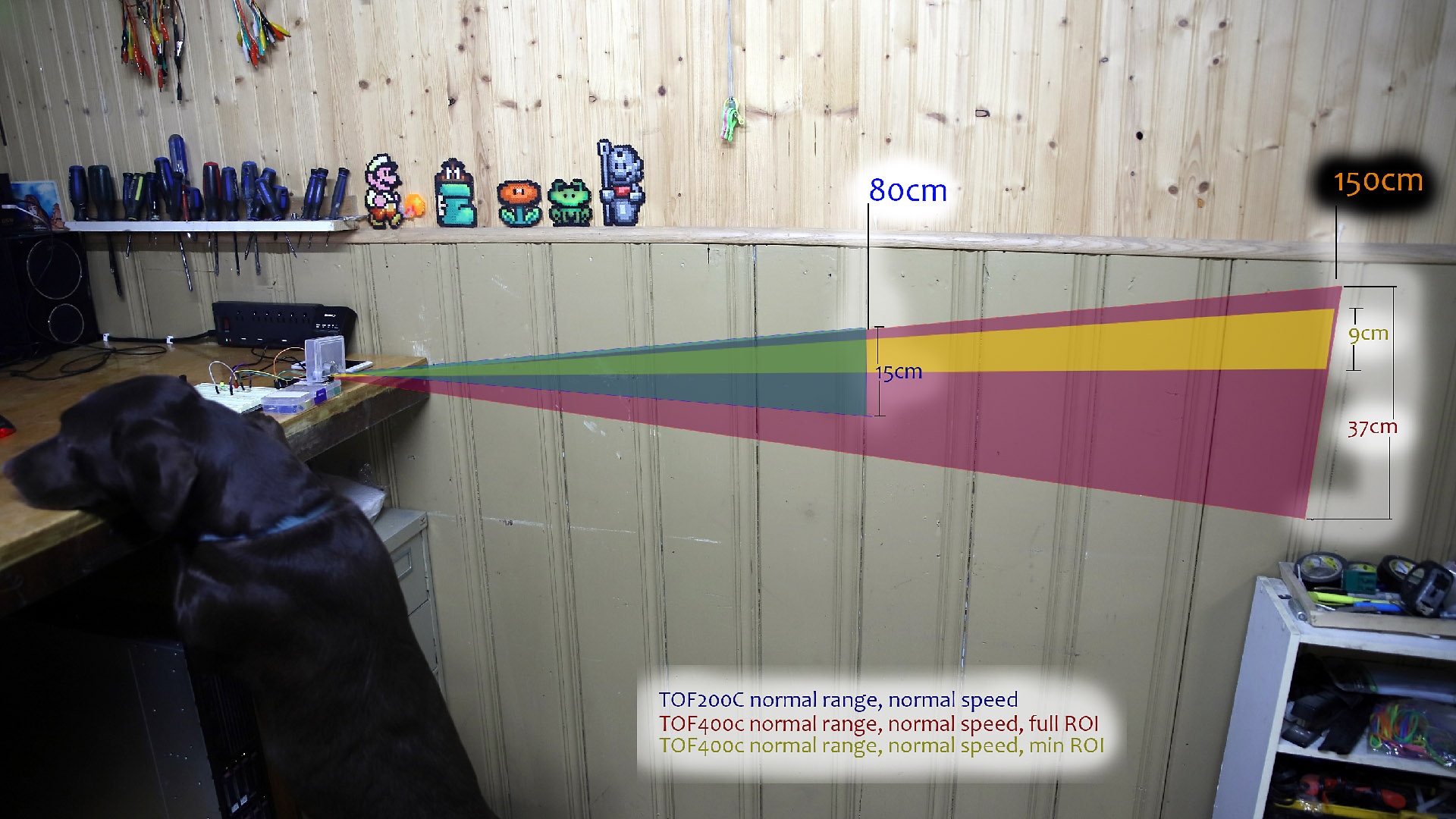
I'm glad it went well for you, I would be curious to hear about what you did with an VL53L01. What where your parameter when setting it up ? It seem to me that in long range mode, the VL53L1X and VL53L0X would need from 30 to 60 seconds to have a precise reading. In short range the 200ms of TOF400c seems to work very well. In short distance mode also if you want a good lock on fix you need to go even closer than advertised maximum. In an attempt to evaluate both sensor, I did try to figure out their range. The TOF400C also have a ROI that seem to act like a crop sensor as it seem to multiply the value returned. My use case is a garage parking indicator, I want to install it near ground level. The sensor will be at around 90cm of the car wheel, so it's too far for a TOF200C but right in the sweet spot of an TOF400C. I did try to evaluate FoV of both sensor by figuring their reliable spot and mark them on the wall, then I could use computer software to draw graphic. It look like when you use 4x4 ROI SPADS (minimum) and keep the Center at 199 then the sensor look upward. I'm my case, it's actually welcome, but I wonder if it's wanted. I wish there was a better way to know where that sensor look and wonder if you have anything to say about it ?ThomasB wrote:I am using the VL53L01 in a project with great success.
Re: enable a device from rules
This seems to be hit and miss on the VL53L0x. ESPEasy sometimes does not know a TOF device has gone missing. Sometimes is does. On the other hand, devices like the LM75A are reliably disabled in the Task if they stop talking.I did try to remove I2C or Current pins of the ToF while this option was on and it would never disable the device.
I am using it to measure milk level in a commercial espresso machine. It is very precise and has been reliable. But my measuring distance is from 30mm to 250mm where as yours is several meters.I would be curious to hear about what you did with an VL53L01.
- Thomas
Re: enable a device from rules
I have to check the source to know for sure about this specific device, but there are some plugins which have the I2C check explicitly disabled as those might show erratic I2C checks. For example if those may not always reply when busy.
So that may explain why some tasks may not be disabled when the sensor is removed.
To explain a bit of history on the automatic disabling of tasks..
When developing the code, you may sometimes (yeah really, only sometimes ) make a mistake which results in a bootloop.
For example divide by zero, not checking a pointer, etc.
So at some point I became a bit annoyed when I had to reprogram a device without the plugin code to regain access to it again.
This resulted in a check to see how often it rebooted without a successful boot.
After 10 of such failed boots, it starts disabling task 1, then task2, etc. until it is able to boot.
Those disabled tasks are not saved as being disabled, so on next boot this happens all over again, until saved.
Then Ton added the check for I2C devices as some libraries we use have explicit "wait forever till we get a reply" and if you set the address wrong or a connector is a bit loose, this is really annoying. (also if a sensor gets wet, it might short some pins thus changing the I2C address)
And as mentioned, some devices do not always reply to I2C scans when put in sleep mode for example (you need to "scan" twice on those) So that's why it might be disabled to do such a check on some I2C plugins.
So that may explain why some tasks may not be disabled when the sensor is removed.
To explain a bit of history on the automatic disabling of tasks..
When developing the code, you may sometimes (yeah really, only sometimes
For example divide by zero, not checking a pointer, etc.
So at some point I became a bit annoyed when I had to reprogram a device without the plugin code to regain access to it again.
This resulted in a check to see how often it rebooted without a successful boot.
After 10 of such failed boots, it starts disabling task 1, then task2, etc. until it is able to boot.
Those disabled tasks are not saved as being disabled, so on next boot this happens all over again, until saved.
Then Ton added the check for I2C devices as some libraries we use have explicit "wait forever till we get a reply" and if you set the address wrong or a connector is a bit loose, this is really annoying. (also if a sensor gets wet, it might short some pins thus changing the I2C address)
And as mentioned, some devices do not always reply to I2C scans when put in sleep mode for example (you need to "scan" twice on those) So that's why it might be disabled to do such a check on some I2C plugins.
Re: enable a device from rules
By the way, if you need to detect a vehicle, maybe a radar sensor is a better option? (or a combination)
I don't know whether those ToF devices may experience bad readings due to reflection.
Would be a nice test to see what those do when pointing at a tilted mirror
Or what if you have some slabs of snow sticking to your car, then the wheel will appear more closer to the sensor.
So if you then depend on it to close the garage door, you may still be in bad luck.
Re: enable a device from rules
This plugin (P113 VL53L1X) does not have that flag set, so should adhere to the Tools/Advanced configuration.
But as mentioned, not all devices always respond in a proper way, so YMMV
/Ton (PayPal.me)
Re: enable a device from rules
Hi everyone, the new design is nearly over and before I install it in the garage to try it out, I though I could do a small presentation of what is done so far. This version will require an USB extension and instead of USB-C, it will power the 5v pin directly as the ESP32C3 will be remote to it's power source now. I also need to wire the LED display, but why hurry, this project is a fun hobby and should remain that way.
On a side note, I would like to say that I hear often the esp32c3 super mini are cheap but I have nothing to complain about my specimen. As I have two of them, I was not very tender with this one while developing the project and my garage is a difficult place for wifi signal. Yet it keep on working surprisingly well with reliable communication over wifi, which will help in diagnostic of installation. What was problematic was ESP32C3 to ToF communication, hopefully this setup will address that situation. Thank you for the recommendation about wire length, Ath. With the 10ft wire using jumper connectors, the censor was reporting very erratic random value. Now that I can solder it using short wire I expect much more precise reading.
I decided to use bigger box as they will need to be adjusted precisely. I intend to attach it to a wood framing re-cut, or something heavy that fit the place.

That black box used to hold the ESP32C3 too and the screw connectors, it was way to much containment for it. Now it will just be 3 wires and some weight I guess.

The ideal setup for me would be under that toolbox and it will be facing the side of the front driver wheel. The distance is around 80 to 100 cm, which is well supported for precise and fast reading on a TOF400C. I estimate the diameter of the region of interest at this area to be around 6cm and fix in about 1/5 sec. The front of the wheel is usually not messy and I dont remember much snow accumulation there. The car has a 23cm clearance so I think the bodywork will remain out of the way and dont fool the reading. Plan B is to try to put the laser in front of the car and detect a frontal area. I would try to avoid that avenue as it mean the laser would need to be on the garage crafting table, and it's no place for delicate electronic.

I also did a test using a tilted mirror and it seem the laser would report the distance of what is being reflected on it. But dont quote me on that, it was a very rough experimentation.
Dont worry about the garage door closing on the car, because of the laser. I hate to admit but it happened in the past, motor detect resistance and the door open back. The laser is just to tell me the car position is optimal so while I can still walk behind it, I have as much space as possible in front. The closing of the door is initiated by me after I made sure everything is in ok, so if something went wrong I'm the one to blame, as usual
On a side note, I would like to say that I hear often the esp32c3 super mini are cheap but I have nothing to complain about my specimen. As I have two of them, I was not very tender with this one while developing the project and my garage is a difficult place for wifi signal. Yet it keep on working surprisingly well with reliable communication over wifi, which will help in diagnostic of installation. What was problematic was ESP32C3 to ToF communication, hopefully this setup will address that situation. Thank you for the recommendation about wire length, Ath. With the 10ft wire using jumper connectors, the censor was reporting very erratic random value. Now that I can solder it using short wire I expect much more precise reading.
I decided to use bigger box as they will need to be adjusted precisely. I intend to attach it to a wood framing re-cut, or something heavy that fit the place.
That black box used to hold the ESP32C3 too and the screw connectors, it was way to much containment for it. Now it will just be 3 wires and some weight I guess.
The ideal setup for me would be under that toolbox and it will be facing the side of the front driver wheel. The distance is around 80 to 100 cm, which is well supported for precise and fast reading on a TOF400C. I estimate the diameter of the region of interest at this area to be around 6cm and fix in about 1/5 sec. The front of the wheel is usually not messy and I dont remember much snow accumulation there. The car has a 23cm clearance so I think the bodywork will remain out of the way and dont fool the reading. Plan B is to try to put the laser in front of the car and detect a frontal area. I would try to avoid that avenue as it mean the laser would need to be on the garage crafting table, and it's no place for delicate electronic.
I remember that thread, it was a fun and early one I read it was great to learn many thing about the ToF laser that way.ThomasB wrote:I am using it to measure milk level in a commercial espresso machine.
If you have anything else to suggest you have all my attention. I searched what radar could be and found the LD2410c are you talking about those ? I'm not sure how they work but they are rather cheap on aliexpress so maybe it would be fun to experiment, unless you had something else in mind ?TD-er wrote:By the way, if you need to detect a vehicle, maybe a radar sensor is a better option?
I also did a test using a tilted mirror and it seem the laser would report the distance of what is being reflected on it. But dont quote me on that, it was a very rough experimentation.
Dont worry about the garage door closing on the car, because of the laser. I hate to admit but it happened in the past, motor detect resistance and the door open back. The laser is just to tell me the car position is optimal so while I can still walk behind it, I have as much space as possible in front. The closing of the door is initiated by me after I made sure everything is in ok, so if something went wrong I'm the one to blame, as usual

Re: enable a device from rules
Yep, those LD24xx ones are the ones I meant.
Those are quite impressive in their accuracy and usefulness.
They typically detect large bags of water (humans/animals) but also metallic surfaces.
It is very hard not to let those radar sensors detect humans when you are in the room as they as that sensitive.
You can change the sensitivity, as there are many parameters to tweak.
So really nice to play with
When using a long USB cable, make sure it won't cause too much voltage drop when the ESP draws some current.
Best to test the setup on your desk with the intended USB cable.
Or add a 5V DC/DC converter to the design and feed it using a higher voltage.
Re: enable a device from rules
Hello TD-er, unfortunately I start to think you are right about usb cable, thankfully my border-line hoarder habit made it so I have bags of those wallwart and I'm pretty sure I have some DC-DC buck convertor around, like the mh-mini-360. Thanks for the heads-up, so I did not searched much when testing the new setup: The laser is rather not very precise in it's reading and end up not being detected at all in the long run when using the long usb cable. As soon as I swap with the short usb-c wire (of course not both as the same time!), everything is back steady and work overnight
I'll add some of those buck convertor in my aliexpress order of LD2410c, I dont think I'll waste time with the bluetooth version, I'm not a fan of wireless... although I start to develop some resentment about wires recently
I'll add some of those buck convertor in my aliexpress order of LD2410c, I dont think I'll waste time with the bluetooth version, I'm not a fan of wireless... although I start to develop some resentment about wires recently
Re: enable a device from rules
I suggest you also order a LD2410b, as that's what I've also been testing with when working on that plugin. There are some small technical differences between those models, and even between sub-versions of the same model, some have to do with communication speed, but that's currently not configurable  . There is some planned work for this plugin, like adding support for LD2420 and LD2450, but haven't started on that yet, too many other projects going already
/Ton (PayPal.me)
Re: enable a device from rules
You could also look into using Ethernet and Power-Over-Ethernet
This way you can make the cable to the node as long as you need it to be.
However this isn't going to make it 'cheap'.
I do have those W5500 PoE modules from m5stack, on which you can mount one of those m5stack Atom modules.
That combination can be had for arount 20-ish euro
Then you have 1 port available via some 4-pin connector with 3V3, GND and 2 GPIO pins.
There are several variations of those ATOM modules, some of which have 25 addressable LEDs, or a display. (not sure how useful those are at a distance as the entire module is roughly 2x2x1 cm.
Of you can buy another Ethernet module and use those PoE injectors (either passive or 802.3af/at)
Re: enable a device from rules
Nah you're just running out on hours per day.
Maybe cut back on those optional time-consuming projects like "sleep"
Re: enable a device from rules
Do you think he his enjoying 3 meals a day too ? Because I see 390 open issues on github, so maybe time prioritization should be reviewed !TD-er wrote:Maybe cut back on those optional time-consuming projects like "sleep"
On a more serious note, I'm now testing a 9v/300ma AC-DC hooked to a 5v buck converter. Hopefully it will hold overnight.
Re: enable a device from rules
Just make sure the wires between the DC/DC converter and the ESP board (+ power to sensors) are thick enough.
Do not use breadboard wires for example.
And not sure Ton has 3 meals a day... I guess at least one of those was scrapped during the last prioritization review
Do not use breadboard wires for example.
And not sure Ton has 3 meals a day... I guess at least one of those was scrapped during the last prioritization review
Re: enable a device from rules
Hi TD-er, yes I would believe the wires to be big enough, they are 0.8mm and are consisting of many small wires twisted together.
Now I'm puzzled, to quickly test the 5v DCDC I plugged it temporarily at 10ft away from the ESP32C3 and ToF, and it worked fine for about 3 days then failed ! So I installed the DCDC inside the box near the ESP32C3 and ToF thinking it would work better but now the laser fail after only a few hours and a TaskEnable or a reboot dont bring back the ToF. So I'm thinking at using a better 10ft wire between the AC-DC and the stepdown DC-DC, maybe the AC-DC is not reliable too, it is rated to 9v but output 14v without load.
Since I'm not using USB anymore to power the ESP32C3 and using it's 5v pin to power the ToF, it seem that an reboot does not re-init the communication to the ToF anymore, so if that is a fact I could bring back the current to ESP32C3 to it's USB connector and power the ToF on the ESP32C3 5v pin. That would provide an easy way to reset the ToF.
There is also that XSHUT pin on the TOF400C that I could try to see if it can be used as a reset switch. This seem simple enough to link to a GPIO pin that turn high/low to momentarily shut down the ToF. Apparently all the kool kids nowaday use a timer to produce some delay, at this point anything goes.
Another option would be to use a relay that provide the power to the ToF that the ESP32C3 could control to reset it. I think I have some relay laying around I could test, or maybe a transistor type relay could be used if it can handle a 5v drive. But before I introduce a relay/transistor in the design or use the USB connector, I'll try to find a better regulated AC-DC, find a better 10' wire and implement the XSHUT pin of the ToF as I have lost confidence anyway in the reliability of those ToF device on the long run and I think a reliable reset mechanism is a necessity.
I wonder if Force Slow I2C speed and I2C ClockStretchLimit: could help me here.
Re: enable a device from rules
Lower I2C speed could help, but only if the I2C communications fail.
To test this, you can try to perform an I2C scan to see if this still works or that the I2C bus might be stalled.
If I2C scan still fails, can you try the following to test if it is really a stuck I2C bus:
- Do not yet power cycle
- Swap the 2 GPIO pins assigned to the I2C bus on the hardware tab (thus swap GPIO pins assigned to SCL/SDA)
- Submit settings
- Try an I2C scan -> this will fail
- Revert the 2 GPIO pins assigned to I2C to their correct settings
- Submit settings
- Try an I2C scan -> should show connected I2C devices.
Re: enable a device from rules
Some questions about your latest configuration:
1. Exactly how long is the i2c cable? Is it really 10 feet?
2. How are the conductors organized in the i2c cable? For example, flat ribbon cable with signals separated by power and ground, or round cable with random conductor positions?
3. What are the values of your i2c pullups and where are they located?
- Thomas
Re: enable a device from rules
Hello TD-er and ThomasB,
TD-er : I have soldered every wires now that I though my project was over but I can de-solder and install jumper cable to test the I2C bus, I will report back if I have the opportunity to check it out!
ThomasB : The I2C cable between TOF400C and ESP32C3 are about 2 or 3 inchs and it's simply 2 wires you can see them there : http://junkskool.net/images/photos/Comp ... x_rear.jpg Also I have no pullup resistor. Is it a basic design requirement I overlooked ?! What would be ideal values ?
Thanks guys, I start to get a bit annoyed at this difficulty and your support is most welcome !
Re: enable a device from rules
You don't need to desolder the wires.
I mean software swap of the clock and data pin.
The reasoning is quite simple but elegant
It is possible for the I2C bus to get 'out of sync' with its devices.
So the device may think it is still replying to the last query, while the master tries to send out a new query.
By swapping (in software) the data and clock line, you can send out an arbitrary amount of 'data bits' which gives the slave device the chance to get rid of its last data bits. (you need to send some data, so that's why you can try to do an I2C scan)
Then just swap it back (in software) and the bus should no longer be 'stuck'.
Re: enable a device from rules
Both SDA and SCL do require a pull-up resistance of roughly 4k7 ... 10k
It is not that critical, but there really should be a pull-up between 3V3 & SDA and 3V3 & SCL (so 2 resistors)
Keep in mind most sensor boards you buy from Ali Express do have such resistors present, so just to make sure you don't create too low resistance as pull-up, you can start with adding 10k resistors.
Re: enable a device from rules
I found that the VL53L1x works best with "strong" pullup resistors. I suggest you leave its two 10K ohm resistors alone (installed on the PCB). But add two new 2.2K ohms, one from 3.3V to SDA and another from 3.3V to SCL. You can do this on the ESP32.
- Thomas
- Thomas
Last edited by ThomasB on 08 Mar 2025, 03:30, edited 1 time in total.
Re: enable a device from rules
Hi TD-er
I'll check the resistor on those TOF400C because there is probably a resistor in there already as you say.
The ToF was failed already so I could try the I2C swap, here is the event of order that I did :
- device dont work and log : VL53L1X: Sensor not found, init failed for 0x29, id: 0xEACC status: 1
- scan work but device is disabled and not found
- swap the pin reverse and submit.
- scan fail
- swap the pin correct and submit.
- scan work
- but log still show error.
reboot or taskenable dont help, I have to power-cycle the TOF to bring it back alive
It seem to me that I really need to reset the TOF400C as it seem to be the one problematic here and the only way to recover. I think to wire the GPIO with XSHUT and add on the activity watchdog timer some high/low sequence on that GPIO to reset the ToF. It seem that pin that are default Low but are set to High in the Hardware tab will have a fraction of second being low during reboot which could be a convenient timer to automatically reset the ToF with every ESP32 reboot.
Re: enable a device from rules
What was done tonight is put a better wire but not changing the AC-DC.
I also found that most people drive the TOF400C VIN with 3.3v not using the level shifter. So I changed the ESP32C3 pin that feed the ToF from the 5v to the 3.3v one and kept the DC-DC to ESP32C3 on the 5v pin.
Then I proceeded to check that I could put a GPIO pin to the XSHUT pin of the ToF. I added a blue LED to see what's going on. On the hardware tab the pin is set to low at boot, but then a Rules on System#Boot bring it back to 1. Effectively shutting that LED for around 2 seconds during every reboot, hibernating the ToF in the meantime. Thanks to that convenient command :
http://[IP Address]/control?cmd=GPIO,5,0
and
http://[IP Address]/control?cmd=GPIO,5,1
I could force a shut of the ToF, awaking the watchdog that would try to enable the device back and eventually initiate a reboot as last recourse. Hopefully the ToF will never jam again and all those protection wont happen too often to make the project useless.
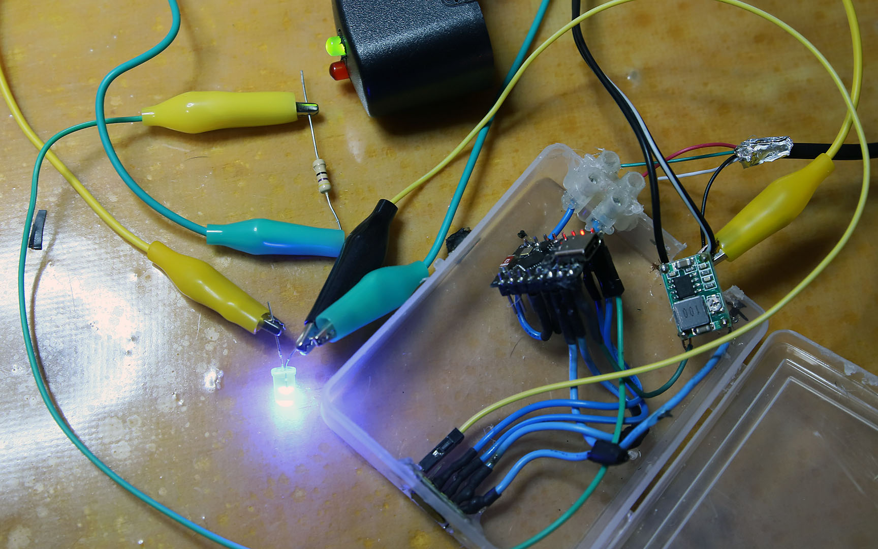
I will test that new setup during some times and see how it goes. I took a picture of my mess, the picture is also bad, this is how everything look when you are so tired
I also found that most people drive the TOF400C VIN with 3.3v not using the level shifter. So I changed the ESP32C3 pin that feed the ToF from the 5v to the 3.3v one and kept the DC-DC to ESP32C3 on the 5v pin.
Then I proceeded to check that I could put a GPIO pin to the XSHUT pin of the ToF. I added a blue LED to see what's going on. On the hardware tab the pin is set to low at boot, but then a Rules on System#Boot bring it back to 1. Effectively shutting that LED for around 2 seconds during every reboot, hibernating the ToF in the meantime. Thanks to that convenient command :
http://[IP Address]/control?cmd=GPIO,5,0
and
http://[IP Address]/control?cmd=GPIO,5,1
I could force a shut of the ToF, awaking the watchdog that would try to enable the device back and eventually initiate a reboot as last recourse. Hopefully the ToF will never jam again and all those protection wont happen too often to make the project useless.
I will test that new setup during some times and see how it goes. I took a picture of my mess, the picture is also bad, this is how everything look when you are so tired

Re: enable a device from rules
Is it possible to add some arrows next to wires to tell which signal is on what wire?
Re: enable a device from rules
Hi TD-er, I understand those pictures are useless at understanding the wiring, I love taking pictures and I think they illustrate the thread. But considering all the help you provide me, they show very little consideration regarding any informative value. I notice how active you are in the ESPEasy community which is my favorite framework firmware, it also save me so much time at diagnosing and using those micro controller which otherwise would be wasted capacity. So I though instead of adding a few arrows as you suggested, I could draw a schematic. To make it clearer all ground that would otherwise be linked to the DC-DC OUT- are just drawn using ground electronic symbol.
Right off the bat I see how silly I was to connect the I2C to pin 6 and 7 of the ESP32. It wont be so complex to solder them to pin 8 and 9 of the ESP32, I dont think it change much but maybe it's faster at device boot as they dont need to be re-mapped. In any case I'll do it for the sake of having things done right.
So far the device is still working reliably. But it's still too soon to say after only 24h of uptime. I would be curious to know how many time the watchdog rectified the situation and I think using the mail notification is the best way to do it. On that ESPEasy mega-20241222 it dont seem to work though, while other esp32 I have running mega-20191208 can send mail. On the mega-20241222 according to the log it seem a connection is made to the server but nothing is sent (Even though I have the same test written than on mega-20191208 body), maybe mail is not avail in COLLECTION_B ? Here is the log on the server :
TCPIP : TCP - [IP] connected to [IP_server]:25.
DEBUG : TCP connection started for session 17211
SMTPD : [IP] SENT: 220 x.y.z
DEBUG : The read operation failed. Bytes transferred: 0 Remote IP: [IP], Session: 17211, Code: 2, Message: End of file
DEBUG : Ending session 17211
on the ESPEasy side here is what is logged :
Email: Error connecting to [IP]:25 Error code: 3
well, at least I guess I can keep an eye for that event in the smtp server indicating a reboot event as I added an notif 1 in the Rules script.
While the XSHUT is effective at resetting the ToF, it can bring it into hibernation where it keep on reporting 0 for Distance, ambient and Direction, effectively fooling my watchdog. But I could improve the Rules script to handle that hypothetical unexpected eventuality with an empty value counter on the watchdog.
If that solution continue to work and the smtp log are not full of reboot event I think I am near an usable project. I'm yet to find a better AC-DC and some good 3 meters pre voltage step-down wire and I'm still waiting for those fixed 5v DC-DC buck converter to arrive next week. So if you have any suggestion to enhance my setup I'll be glad to consider them in the meantime.
Cheers !
Code: Select all
On System#Boot do
 GPIO,3,0 //setup led init state
 GPIO,4,1
 GPIO,5,1 //close the XSHUT pin
 LooptimerSet,1,5 // keep ToF enabled via TaskEnable
 LooptimerSet,2,10 // keep ToF enabled via Reboot
 TaskValueSet 1,1,0 // reset TaskEnable challenge
 TaskValueSet 1,2,0 // reset Reboot challenge
 TaskValueSet 1,3,0 // reset Stalled counter
 If [TOF400C#settings.enabled]=0
  TaskEnable TOF400C //make sure the TOF is enabled, in case a submit was made while disabled.
 Endif
 notify 1 // send an email we rebooted
Endon

On TOF400C#All do
 TaskValueSet 1,1,1 // sensor is alive, fulfill TaskEnable challenge
 TaskValueSet 1,2,1 // sensor is alive, fulfill Reboot challenge
 If [TOF400C#Distance]=0 And [TOF400C#Ambient]=0 And [TOF400C#Direction]=0
  TaskValueSet 1,3,[WATCHDOG#Stalled]+1 // add to the stalled waterlevel
 Else
  TaskValueSet 1,3,0 // something sensical received, flush waterlevel
 Endif
 If [TOF400C#Distance]>600
  GPIO,3,1 // something is detected swap lights !
  GPIO,4,0
 Else
  GPIO,3,0 // not anymore
  GPIO,4,1
 Endif
Endon

On Rules#Timer=1 do //TaskEnable watchdog
 If [WATCHDOG#Enabled]=0
  TaskEnable TOF400C // Enable Task
 Else
  TaskValueSet 1,1,0 // sensor is alive, reset it's watchdog challenge
 Endif
Endon

On Rules#Timer=2 do //Reboot watchdog
//failed reboot challenge mean no activity OR 10 reading all 0 mean stalled, reboot
 If [WATCHDOG#Reboot]=0 Or [WATCHDOG#Stalled]>10
  Reboot
 Else
  TaskValueSet 1,2,0 // sensor is alive, reset it's watchdog challenge
 Endif
EndonRe: enable a device from rules
For now I will just focus on the 'schematics' you made.
I do have a few remarks of things for you to keep in mind or check.
First of all the SHUT pin, which is connected to accross the LED.
Why not in this order:
GND --- LED --- Resistor --- SHUT pin --- GPIO-5
By placing it in this order, you will toggle between 0V and 3V3.
The way you have it wired now, the voltage on the SHUT pin will be equal to the voltage drop of the LED, which depends on the color of the LED.
For example a red LED has a voltage drop of typically 1.8V
It is possible the board also has a pull-up resistor to "VIN" and thus the voltage may never drop far enough to make a clear switch in logic level and thus show undefined behavior.
Please take a look at the datasheet, linked here: https://www.st.com/en/imaging-and-photo ... 53l1x.html
On page 6, there is a table with suggested pull-up resistors for the I2C bus.
The mentioned pull-up resistor values in this table are quite a bit lower than typically used on most boards.
So maybe it may help to add another 4k7 pull-up resistor between SDA & 3V3 and SCL & 3V3.
This would then be parallel to an already present resistor, so the actual resistance will be smaller.
I don't know what the actual load capacitance of your cables is, so you might need to experiment.
Things to keep in mind:
- Load capacitance depends on length of the cable and how close the wires are to eachother.
- Higher clock frequency needs faster switching of a signal, thus stronger pull-up resistors.
So if you still experience issues with I2C stability, you can lower the I2C clock frequency and/or lower the pull-up resistance. (or shorten the wire length, but that isn't so practical in most 'challenging' setups)
Another possible issue you may experience is that the I2C is working at a frequency which may be close to the switching frequency of the DC/DC converter.
So you may want to use twisted wire (like in UTP network cable) to connect your sensor and/or your power.
- 1 pair for SDA & GND
- 1 pair for SCL & GND
- 1 pair for 3V3 & GND
This leaves 1 pair which you could use to carry the 5V from the DC/DC module back to the ESP if this needs to be over the same path.
Each pair of wires in an UTP cable does have different number of twists per distance, so they won't interfere with eachother.
Also you may want to add some capacitors as close as possible to the VIN/GND on the sensor and in the 5V/GND of the ESP.
For example 100 nF ... 1 uF at the sensor and 22 uF ... 220 uF at the ESP.
The actual values aren't that critical. Just make sure that the ones with a specific polarity (probably the one at the ESP side) is mounted with the correct polarity or else you will hear a (very) loud bang.
I think the AC adapter might be a bit underpowered at 300 mA, even though it is outputting at a higher voltage and you are using a DC/DC adapter.
Problem with those 300 mA power adapters is that they often react quite slow at changes in current demands, which may show at the output of the DC/DC module. That's why I suggest to add a capacitor close to the ESP.
Not sure if the 3m long cable for the LEDs can also act as an antenna and cause issues at the ESP.
You could add a small 100 nF capactor over GPIO4 / GND and GPIO3 / GND. This will dampen any received high frequency noise. I assume those are just signalling LEDs and do not need to be switches at high frequency, right?
The capacitor will dampen the maximum frequency you can send to the LEDs.
I think the 50 Ohm resistor you're using from any GPIO to the LED is a bit low.
Just assume those are red LEDs, then there will be (3V3 - 1V8) = 1.5V over the resistor.
At 50 Ohm, this is 30 mA.
This is way more than typically needed for a LED and worse, it is probably about the max. (or more) of what a GPIO pin might source.
Maybe best to at least change it to 100 Ohm.
Regarding what pin to use, please take a look at this part of the docs: https://espeasy.readthedocs.io/en/lates ... n-esp32-c3
As you can see, GPIO 8 and 9 are "boot strapping pins", which means they need to have a specific state at boot.
When wiring to a pull-up resistor, like on I2C, you will have no boot issues.
So better not wire those to something which may pull the pin down at boot (e.g. some switch)
Re: enable a device from rules
About the mail notifier issues, you may want to try one of the later builds as Ton made a fix recently related to sending emails to a non-SSL server (using port 25)
For example this test build: https://td-er.nl/ESPEasy/latest/
For example this test build: https://td-er.nl/ESPEasy/latest/
Re: enable a device from rules
Hello TD-er, thanks for that reply, you suggest many upgrade I can apply. I have noted all the resistor and capacitors listed and will order some kit from aliexpress since I dont have much of them. I understand they will make the system more stable.
I think the UTP cable is a very clever idea I can implement without too difficulty.
The led I have are ultra-bright and rated 2.6-3.6v so I though a resistor would not be necessary but my father insisted so much I added some that I put those. Although I see the red one is 1.8-2.3v and overlooked it's rating, but it's the one sparingly lit so I guess it did not burned already but I'm clearly over-volting it, will fix that ASAP.
About the I2C pins I understand that I should not change them. Ok I can do that
The good news is that in 24h I received 1 notification of a reboot. Because of the state of the mail service I cannot know the exact cause. I'll take a look at the test build, maybe an easy OTA would work on an ESP32C3, otherwise I'll just use a backup, I'm sure it work very well. Btw I dont think the SSL work, I did not tested it much as I assumed both where broken but I'll check it out with more instance, if it work I can just use that.
Since I use alligator wire on the XSHUT line it was easy to make the modification you suggest (put the XSHUT between GPIO5 and resistor). I would expect that change to fix an odd behavior but it did not. When I disconnect the pin-5 the led remain dimly light, as if some current was leaking from the XSHUT. Maybe it's from the pull-up setup from the host board.
What I will do in the meantime I receive my kits is try to update the graphic with the resistors and caps as I understand some will bridge two wires and wont be in series. I'm always worried to fry short something when doing so, I would hence appreciate very if you validate the implementation of your suggestion and I will make them easy to see. As you have probably noticed I am not very good at electronic. I will also read about those pull-up resistors as I realize I cannot pretend to know what they are anymore
Many thanks, bye
Re: enable a device from rules
You really need a resistor in series of the LED.
The reason is quite simple. A LED is a diode, which isn't acting like any 'normal' parts like a resistor or an old fashioned light bulb (which is a resistor).
A diode will block any current until the voltage over the LED exceeds some threshold.
Then it will fully conduct.
So if you don't have a resistor in series, the current will be as much as your GPIO pin can deliver.
Meaning either the GPIO may try to limit the current or burn, or the LED will get damaged.
This threshold also acts as some kind of voltage regulator and will try to keep the voltage over the LED as constant as possible.
That's why you need to have the logic pin to the XSHUT pin connected to the GPIO and not to the LED.
How do you make the SHUT pin "low" ?
When you send a command like "gpio,5,0", it should strongly pull that pin to GND and the LED should not glow anymore.
Before you make the changes, can you first draw whatever you need to change so we can check it first?
It will also help you understand more what needs to be done and why.
Re: enable a device from rules
Hello, so I have applied all TD-er recommendation to the new version of the schematic. You will see in blue the added capacitors and resistances. What have also changed is the AC-DC, I have found a 5v 1.5a that output 7.5v and seem much more capable of providing power to the project. Also I wont use the XSHUT pin of the ToF anymore. I will soon receive some 5v -> 3.3v DCDC that have an EN pin, so I will be able to completely reset the ToF instead of putting it into hibernation which could produce some odd result that needed to be addressed by watchdog Rules, I realize it was not meant for that. You see I noted a resistor symbol next to a ? between GPIO 5 and EN pin of the DCDC, would you think a resistor might be needed here ? ChatGPT suggest I add something between 4k7 and 10k. I should receive all my electronic parts next week, I'm really eager to mount that on a protoboard.
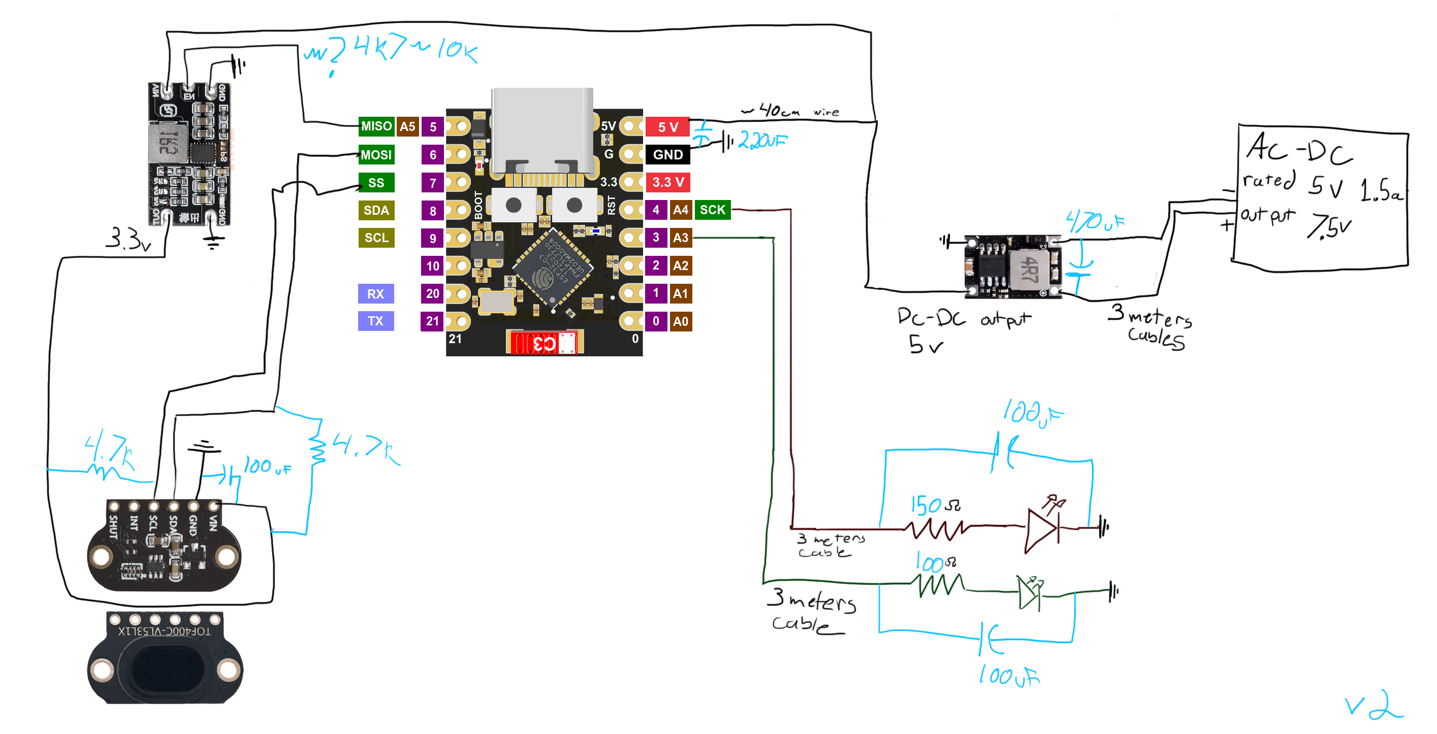
I use the ToF in low speed mode, I read it at 200ms in normal 130cm range. This seem to be the ideal setup for speed and accuracy for my project need. I was able to use the latest release and now the mail work. I can see the ESP32C3 reboot around 10 times a day. When it is rebooted from the stalled or reset watchdog the counter value of the Dummy device should be kept so I can detect the reason. But in nearly every case, it seem to be rebooted for another reason as the %bootcause% is 10 but the Dummy device values indicates no problem detected with the ToF. The mail I receive 99% of the time is the "%lcltime_am% rebooted for unknown reason (%bootcause%)" from the Else of the If [WATCHDOG#Reboot]=0 Or [WATCHDOG#Stalled]>5 instruction. Which mean the reboot was not initiated by the On Rules#Timer=2 do timer reboot instruction. Is there is anything that could help me diagnostic what else caused it to reboot ? Is there is any case a reboot will reset the value of a Dummy device ? For that matter, is there is a way I could send in the mail the value of [WATCHDOG#Reboot] Dummy device ?
I use the ToF in low speed mode, I read it at 200ms in normal 130cm range. This seem to be the ideal setup for speed and accuracy for my project need. I was able to use the latest release and now the mail work. I can see the ESP32C3 reboot around 10 times a day. When it is rebooted from the stalled or reset watchdog the counter value of the Dummy device should be kept so I can detect the reason. But in nearly every case, it seem to be rebooted for another reason as the %bootcause% is 10 but the Dummy device values indicates no problem detected with the ToF. The mail I receive 99% of the time is the "%lcltime_am% rebooted for unknown reason (%bootcause%)" from the Else of the If [WATCHDOG#Reboot]=0 Or [WATCHDOG#Stalled]>5 instruction. Which mean the reboot was not initiated by the On Rules#Timer=2 do timer reboot instruction. Is there is anything that could help me diagnostic what else caused it to reboot ? Is there is any case a reboot will reset the value of a Dummy device ? For that matter, is there is a way I could send in the mail the value of [WATCHDOG#Reboot] Dummy device ?
Code: Select all
On System#Boot do
 If [WATCHDOG#Reboot]=0 Or [WATCHDOG#Stalled]>5// send an email we rebooted
  If [WATCHDOG#Reboot]=0
   notify 1, "%lcltime_am% watchdog rebooted cause (%bootcause%) : Reboot = 0"
  Endif
  If [WATCHDOG#Stalled]>5
   notify 1, "%lcltime_am% watchdog rebooted cause (%bootcause%) : Stalled > 5"
  Endif
 Else
  notify 1, "%lcltime_am% rebooted for unknown reason (%bootcause%)"
 Endif
 GPIO,3,0 //setup led init state
 GPIO,4,1
 GPIO,5,1 //close the XSHUT pin
 LooptimerSet,1,5 // keep ToF enabled via TaskEnable
 LooptimerSet,2,10 // keep ToF enabled via Reboot
 TaskValueSet 1,1,0 // reset TaskEnable challenge
 TaskValueSet 1,2,0 // reset Reboot challenge
 TaskValueSet 1,3,0 // reset Stalled counter
 If [TOF400C#settings.enabled]=0
  TaskEnable TOF400C //make sure the TOF is enabled, in case a submit was made while disabled.
 Endif
Endon

On TOF400C#All do
 TaskValueSet 1,1,1 // sensor is alive, fulfill TaskEnable challenge
 TaskValueSet 1,2,1 // sensor is alive, fulfill Reboot challenge
 If [TOF400C#Distance]=0 And [TOF400C#Ambient]=0
  TaskValueSet 1,3,[WATCHDOG#Stalled]+1 // add to the stalled waterlevel
 Else
  TaskValueSet 1,3,0 // something sensical received, flush waterlevel
 Endif
 If [TOF400C#Distance]>600
  GPIO,3,1 // something is detected swap lights !
  GPIO,4,0
 Else
  GPIO,3,0 // not anymore
  GPIO,4,1
 Endif
Endon

On Rules#Timer=1 do //TaskEnable watchdog
 If [WATCHDOG#Enabled]=0
  TaskEnable TOF400C // Enable Task
 Else
  TaskValueSet 1,1,0 // sensor is alive, reset it's watchdog challenge
 Endif
Endon

On Rules#Timer=2 do //Reboot watchdog
//failed reboot challenge mean no activity OR 10 reading all 0 mean stalled, reboot
 If [WATCHDOG#Reboot]=0 Or [WATCHDOG#Stalled]>5
  Reboot
 Else
  TaskValueSet 1,2,0 // sensor is alive, reset it's watchdog challenge
 Endif
Endon
Who is online
Users browsing this forum: Amazon [Bot] and 18 guests