enable a device from rules
Moderators: grovkillen, Stuntteam, TD-er
Re: enable a device from rules
Not sure if I read your handwriting correctly, but the 100 nF capacitors seem to be written down as "uF", which is 1000x larger capacity.
Re: enable a device from rules
Also I don't understand what you mean with the text next to the power supply.
5V 1.5A and then outputting 7.5V ?
You didn't by any chance measure the voltage of a transformer without any load?
If so, then I think it will cause issues as that voltage will drop under load, probably below the minimal input voltage of your DC/DC converter.
Also the 100 nF (not uF) capacitors you have draw over the LEDs should be close to the GPIO pins of the ESP board.
These are quite small, so it should not be an issue.
The reason behind this is that the long cabled to the LEDs might act as an antenna and could pick up quite a strong noise from the DC/DC converters which may cause strange behaviour in the ESP.
By adding those capacitors, a lot of the picked up noise will be absorbed by the capacitors and the signal entering the ESP will have much less energy left.

Re: enable a device from rules
Hello TD-er !
It was a mistake, I wrote 100uf but I meant 100nf, after some consideration though I decided I will put an 1uf there if possible. It was in the range of your recommendation.
You are absolutely right about the no-load output of the AC-DC. I'm sorry I should had made that clear. I measured the no-load output to know the regulation performance quality of the AC-DC. Under my project load, and after a ~3 meters wire, that 5v 1.5a (7.5v no-load) output 6.9v so I think this new power supply I found is a good match for my project.
So I integrated all your comments to that version 3 of the schematic.
- the 100uf are drawn to show they should be near the ESP32C3.
- the TOF now use a 1uf capacitor.
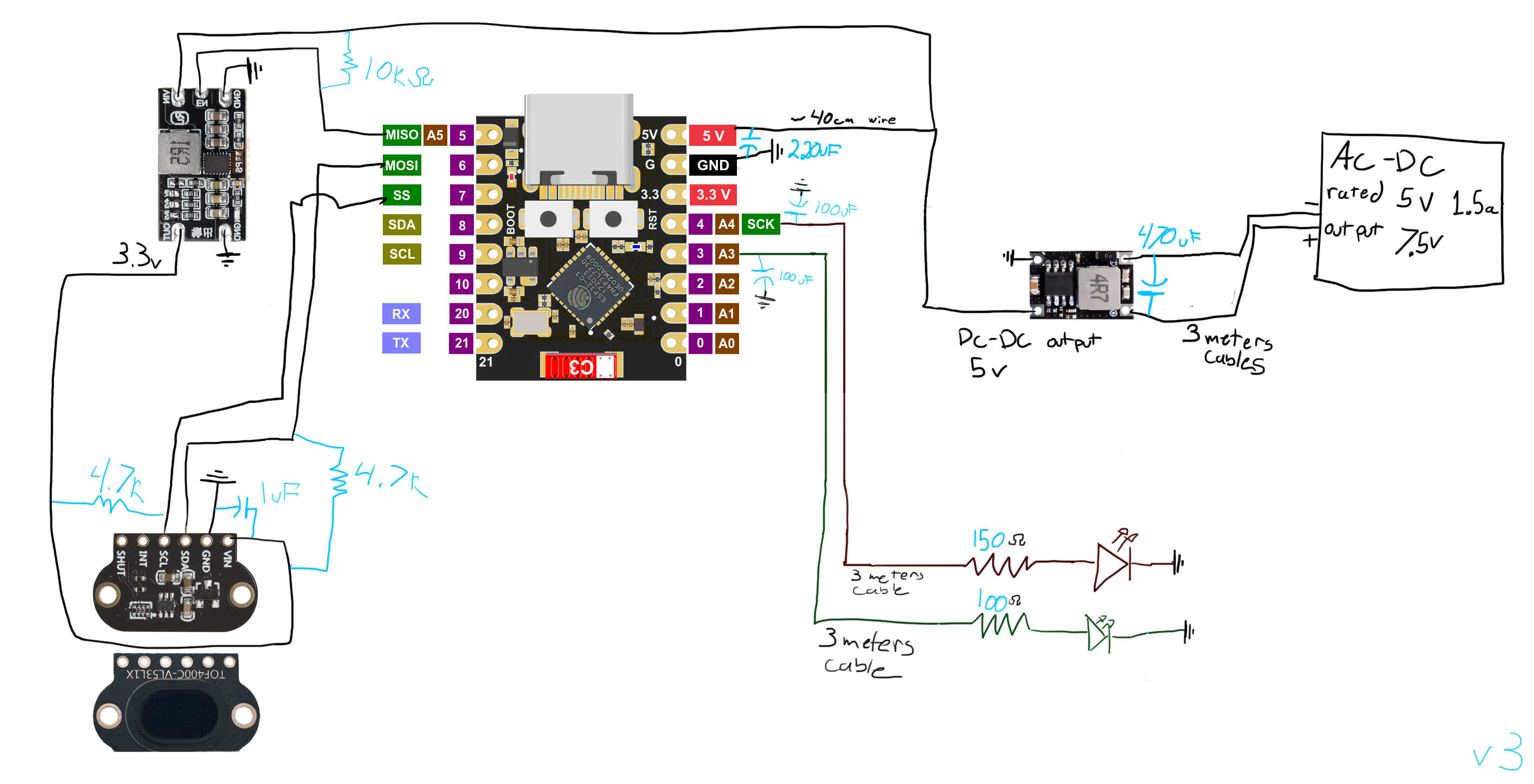
I should receive the parts this week and build the board soon. Since I activated mail notification, it will be easy to know the impact of the components addition on the system (now the ESP reboot around 20 times a day). I understand by the fading amount of your recommendation that I'm near a good design and nothing obvious should fry those parts (not that they cost much anyway). If that ever happen I'll of course only blame myself and my sketchy schematic. I'm also very aware of all the help you provided me and once that project will be over I'll certainly consider a donation to ESPEasy !
It was a mistake, I wrote 100uf but I meant 100nf, after some consideration though I decided I will put an 1uf there if possible. It was in the range of your recommendation.
You are absolutely right about the no-load output of the AC-DC. I'm sorry I should had made that clear. I measured the no-load output to know the regulation performance quality of the AC-DC. Under my project load, and after a ~3 meters wire, that 5v 1.5a (7.5v no-load) output 6.9v so I think this new power supply I found is a good match for my project.
So I integrated all your comments to that version 3 of the schematic.
- the 100uf are drawn to show they should be near the ESP32C3.
- the TOF now use a 1uf capacitor.
I should receive the parts this week and build the board soon. Since I activated mail notification, it will be easy to know the impact of the components addition on the system (now the ESP reboot around 20 times a day). I understand by the fading amount of your recommendation that I'm near a good design and nothing obvious should fry those parts (not that they cost much anyway). If that ever happen I'll of course only blame myself and my sketchy schematic. I'm also very aware of all the help you provided me and once that project will be over I'll certainly consider a donation to ESPEasy !

Re: enable a device from rules
I think you missed the comment TD-er made?
And more in general, for driving LEDs, it's better to wire them 'upside-down', ie. from 3V3 to the GPIO (with the resistor in-line), and pull the GPIO low to enable the LED, as such GPIO can source max. about 5 mA, but sink (to GND) up-to 20 mA.
1 uF for power-decoupling is a bit small, one (or both) of the 100 uF capacitors would be a better choice.
/Ton (PayPal.me)
Re: enable a device from rules
Well for low-power stuff like sensors, 100 nF ... 1 uF is often "good enough". (unless the ToF sensor is one of those more demanding circuits...)
For more power demanding circuits, especially when they might draw higher current spikes, you may need higher capacitance.
Typically for an ESP, you need between 22 uF ... 220 uF.
I think Ton's remark about changing the LEDs makes sense.
Something this:
Code: Select all
3V3 --- Resistor --- LED --- GPIO.
Delivering (source) 3V3 via a GPIO to power a LED can often deliver way less power compared to what a GPIO can "sink" internally to GND.
And no 100 uF for the LEDs, rather 100nF.
When using 100 uF for the LEDs, it takes quite a long time to turn a LED on/off and I don't think the GPIO pin will like drawing much power for a longer time. (charging an empty capacitor is electrically like a short circuit)
Re: enable a device from rules
I'm so sorry I missed the TD-er comment, thanks for figuring that out, Ton.
What I did in version 4 is to put a 10uF cap at the ToF as it seem to be a good settlement for that part.
I also changed the 100uF to 100nF capacitor near the ESP32C3. I have put the LED and their respective resistor in a grey box to highlight it's a box external to the main project. I also reversed them, thanks for making the edit easy to understand for me. I understand I will need to adjust the code to take into consideration that modification but this kind of adjustment really is the icing on the cake.
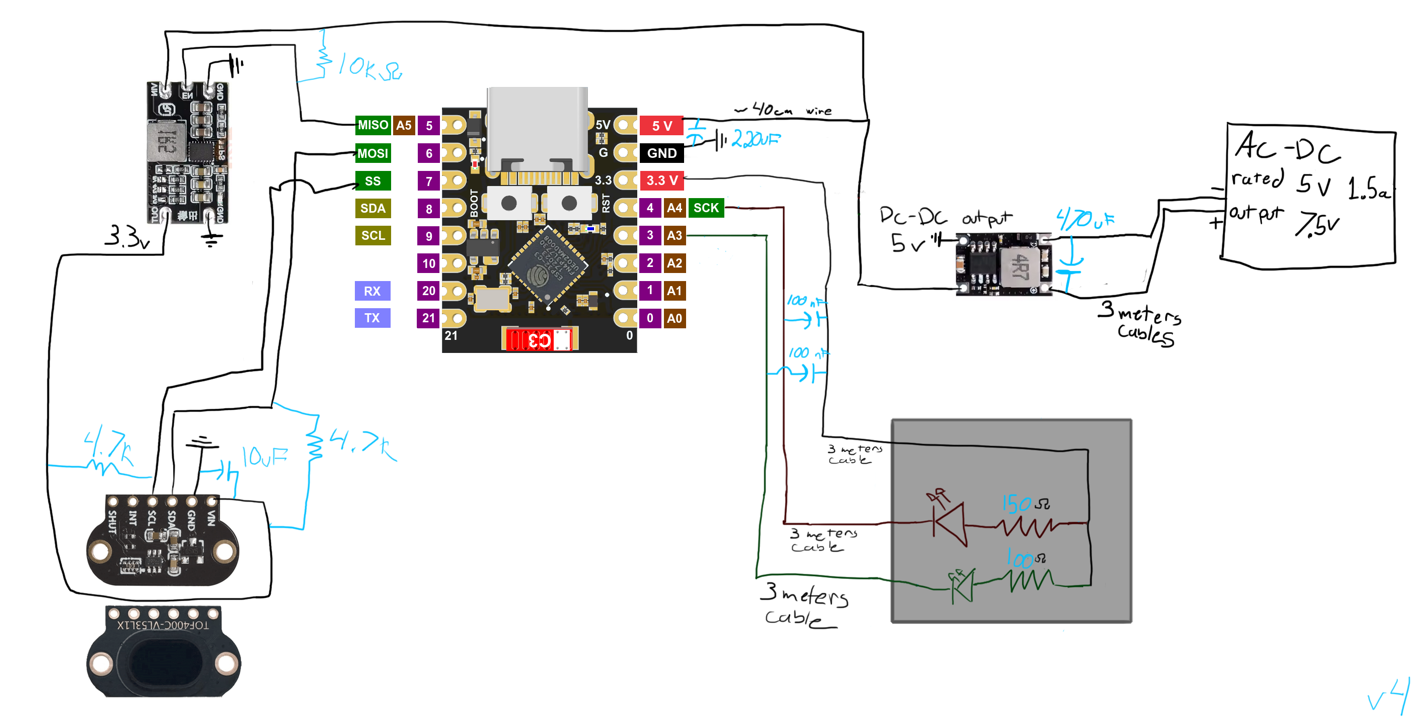
Thank you so much Ath and TD-er, your help is very much appreciated !
What I did in version 4 is to put a 10uF cap at the ToF as it seem to be a good settlement for that part.
I also changed the 100uF to 100nF capacitor near the ESP32C3. I have put the LED and their respective resistor in a grey box to highlight it's a box external to the main project. I also reversed them, thanks for making the edit easy to understand for me. I understand I will need to adjust the code to take into consideration that modification but this kind of adjustment really is the icing on the cake.
Thank you so much Ath and TD-er, your help is very much appreciated !

Re: enable a device from rules
I don't see anything wrong in your drawing.
When soldering the capacitors (those in the uF range) make sure to mount them with the correct polarity.
You will be notified with a loud bang if you wired them in the wrong direction.
When soldering the capacitors (those in the uF range) make sure to mount them with the correct polarity.
You will be notified with a loud bang if you wired them in the wrong direction.
Who is online
Users browsing this forum: No registered users and 15 guests