Hello,
I use a waveshare ESP32-C6-Zero with a TCA9548A 8-channel I2C multiplexer to read out different BM-280 sensors. Build: ESP_Easy_mega_20241222_normal_ESP32c6_4M316k_LittleFS_CDC_ETH Dec 22 2024
I get no connection to the multiplexer and I2C scan cannot find the multipelxer but I think everything is connected correct. A0 / A1 / A2 is connected with ground, adress should be 0x70. Vin 5V and correct SDA and SCL. Any idea ?
It is not possible to enable my BM-280 device.
Thank you
Regards
Thomas
Here are some screenshots:
I2C multiplexer problem
Moderators: grovkillen, Stuntteam, TD-er
-
obstbauer
- Normal user
- Posts: 85
- Joined: 25 May 2023, 15:46
I2C multiplexer problem
You do not have the required permissions to view the files attached to this post.
-
Ath

- Normal user
- Posts: 4620
- Joined: 10 Jun 2018, 12:06
- Location: NL
Re: I2C multiplexer problem
Hmm, I wouldn't use Vin of 5V, as the entire I2C bus on an ESP32 is 3.3V exclusively.
Also double-check you have SDA and SCL connected correctly, and have added pull-up resistors (10k is fine), as by default these multiplexer boards don't have them installed, and they are required for the bus between the ESP and the multiplexer to work.
Edit: I assume the BMx280 worked OK without the multiplexer?
/Ton (PayPal.me)
-
TD-er
- Core team member
- Posts: 10333
- Joined: 01 Sep 2017, 22:13
- Location: the Netherlands
Re: I2C multiplexer problem
I think it is indeed related to no present I2C pull-up resistors.
The multiplexer input and outputs do not have pull-up resistors present.
Most sensor boards, like the BME280 etc. do have pull-up resistors present, so you likely don't need to add those on the multiplexed outputs.
But you need to add a resistor between SDA and 3V3 on the ESP side and the same between SCL and 3V3 on the ESP side.
Actual resistance isn't that important, as long as it is somewhere between 3k3 and 10k.
However I do think it should be the same value for both SDA and SCL or else the timing of data and clock may not be in sync.
-
obstbauer
- Normal user
- Posts: 85
- Joined: 25 May 2023, 15:46
Re: I2C multiplexer problem
I don't have pull-ups.
I will add them, thank you for the advice !!!
I will add them, thank you for the advice !!!
-
obstbauer
- Normal user
- Posts: 85
- Joined: 25 May 2023, 15:46
Re: I2C multiplexer problem
I added two pull-ups with 4.7 kOhm and connected the multiplexer to 3,3V, but still the same problem
I2c scan finds nothing
I2c scan finds nothing
-
obstbauer
- Normal user
- Posts: 85
- Joined: 25 May 2023, 15:46
Re: I2C multiplexer problem
the BM280 is found by the i2c scan
-
Ath
- Normal user
- Posts: 4620
- Joined: 10 Jun 2018, 12:06
- Location: NL
Re: I2C multiplexer problem
Can you share a close-up photo of the board, where the pin names can be read?
/Ton (PayPal.me)
-
TD-er
- Core team member
- Posts: 10333
- Joined: 01 Sep 2017, 22:13
- Location: the Netherlands
Re: I2C multiplexer problem
Also can you make a simple drawing showing what is connected to which pins?
Also double check you didn't mix up SDA and SCL to the input of the multiplexer.
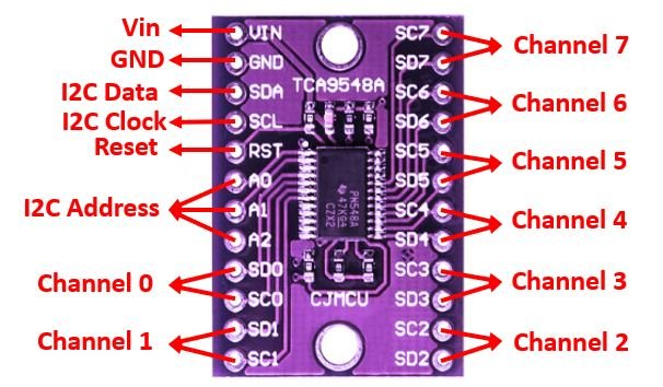
So the ESP is on the "I2C Data" (connected to ESP's SDA) and "I2C Clock" (connected to ESP's SCL)
These SDA/SCL then have a pull-up resistor connected to 3V3.
The multiplexer is then powered by 3V3.
You may have to double check the RST isn't by accident shorted with some pin.
Not 100% sure if it can be left floating. See the datasheet: https://www.ti.com/lit/ds/symlink/tca9548a.pdf (page 3)
A0...A2 probably can be left floating, but when in doubt pull them to GND or 3V3 to make sure the I2C address is fixed.
Maybe easiest to connect RST, A0 ... A2 to 3V3 as they are next to eachother.
Then some sensor with its SDA connected to "SDx" and SCL connected to "SCx".
Also double check you didn't mix up SDA and SCL to the input of the multiplexer.
So the ESP is on the "I2C Data" (connected to ESP's SDA) and "I2C Clock" (connected to ESP's SCL)
These SDA/SCL then have a pull-up resistor connected to 3V3.
The multiplexer is then powered by 3V3.
You may have to double check the RST isn't by accident shorted with some pin.
Not 100% sure if it can be left floating. See the datasheet: https://www.ti.com/lit/ds/symlink/tca9548a.pdf (page 3)
So better pull-up the RST to 3V3.Active-low reset input. Connect to VCC or VDPUM (1) through a pull-up resistor, if not used
A0...A2 probably can be left floating, but when in doubt pull them to GND or 3V3 to make sure the I2C address is fixed.
Maybe easiest to connect RST, A0 ... A2 to 3V3 as they are next to eachother.
Then some sensor with its SDA connected to "SDx" and SCL connected to "SCx".
-
obstbauer
- Normal user
- Posts: 85
- Joined: 25 May 2023, 15:46
Re: I2C multiplexer problem
this is how it is connected now, I will add an aditional pull-up for reset
You do not have the required permissions to view the files attached to this post.
-
TD-er
- Core team member
- Posts: 10333
- Joined: 01 Sep 2017, 22:13
- Location: the Netherlands
Re: I2C multiplexer problem
Just based on the photo, it seems like there is already a pull-up resistor connected between RST and 3V3.
Can you also check if SDA/SCL are not swapped in the ESPEasy config?
You can also swap both I2C pins in ESPEasy to see if this makes a difference.
Can you also check if SDA/SCL are not swapped in the ESPEasy config?
You can also swap both I2C pins in ESPEasy to see if this makes a difference.
-
ThomasB

- Normal user
- Posts: 1479
- Joined: 17 Jun 2018, 20:41
- Location: USA
Re: I2C multiplexer problem
I have a few of those I2C multiplexers, still in the bag. Mine are silkscreen labeled with HW-617 instead of CJMCU.
I looked at one and can confirm that SDA, SCL, and RST all have 10K ohm pullups. The address inputs are floating.
From the info provided so far, the basic wiring appears correct. But one important wiring item has not been discussed. That is, how long are all the wires going to the multiplexer?
Until you have success with it, they need to be kept short. Perhaps under 10cm. After it is working you can try longer wires, if needed.
- Thomas
-
TD-er
- Core team member
- Posts: 10333
- Joined: 01 Sep 2017, 22:13
- Location: the Netherlands
Re: I2C multiplexer problem
One more idea...
is there something connected to one of multiplexer output ports which might cause an I2C address conflict with the multiplexer?
is there something connected to one of multiplexer output ports which might cause an I2C address conflict with the multiplexer?
-
obstbauer
- Normal user
- Posts: 85
- Joined: 25 May 2023, 15:46
Re: I2C multiplexer problem
after a holiday break of my project I made some progress.
I changed the multiplexer (no additional pull ups, and floating A0,A1,A2), new cables and I used a dispaly instead of a BME280 and it works....
I recognized by tests with the BME-280 and the display that my test BME280 is maybe damaged because it becomes hot by powering. This was my test setup for my actual project. I want to read out 3x BME280 (cable lengths 20 cm to 2 m) and one display. All the sensors worked before with two ESP32C3 super minis, which are maybe fake bad boards with instalbe wifi. So I wanted to do everything wtih one new ESP32-C6-Zero from waveshare with the multiplexer. I guessed that I only have to connect everything to my succesful tested setup C6 and multiplexer and it works, but It doesn't work....
Now I see that the i2c scan always confuse my ESP board. If I connect only the display to the multiplexer, it works. If I connect one ore more of the BME280 and make a I2c scan the ESP crashes and I need a restart by powering off and on. It makes no difference if I connect it directly to the ESP or over the multiplexer. I don't understand why my BME-280 sensors seem to confuse my C6 board ? Maybe the pull-up design between the C3 and the C6 is different ?
I can try to to use another board to test the BME-280 sensors...
I connected all the sensors and the multiplexer to the 3,3V pin of the C6 and GND. The C6 is powered with 5V from USB connector.
Any ideas?
-
Ath
- Normal user
- Posts: 4620
- Joined: 10 Jun 2018, 12:06
- Location: NL
Re: I2C multiplexer problem
It's rather unusual for the ESP to crash on an I2C scan, as that's not an expected scenario. It just tries to communicate with a device on an I2C address over the configured bus(es) and multiplexers (using the Slow speed setting) to see if there's a response. This sort-of implies that these settings should not be (and should never be) set to 0!
Swapping the SDA and SCL pins (accidentally) will normally just give no result during an I2C scan, and even though I have seen some sensors respond with that configuration, that's again quite unusual.
Possibly an electronics failure in your sensor is causing this. Did you take ESD prevention measures when handling the sensor?
/Ton (PayPal.me)
-
obstbauer
- Normal user
- Posts: 85
- Joined: 25 May 2023, 15:46
Re: I2C multiplexer problem
I made more tests yesterday. The BME-280 with the shortest cable (20cm) runs with display and multiplexer. If I connect a further BME-280 with longer cable (it makes no difference if I connect directly or to the multiplexer) the described problems appear.
It seams that it has something to do with the cable length. I know that i2c is sensitive to the cable length but the boards I used before had no problems with the same 2 m cables and I use a ESP8266 with the same type of sensor and wide more than 5 m cable without problems. So I don't expect this... I will try C3 boards I used before again to see if the sensors work with the long cables.
Did you take ESD prevention measures when handling the sensor?
No, how should I do that ?
-
Ath
- Normal user
- Posts: 4620
- Joined: 10 Jun 2018, 12:06
- Location: NL
Re: I2C multiplexer problem
I2C doesn't tolerate long cables (over 30 cm!) very well, so keeping cable length as short as possible is most advisable. One way of doing that is placing the ESP in the middle, between the two sensors, so they have similar cable length.obstbauer wrote: 23 Jul 2025, 16:20 I made more tests yesterday. The BME-280 with the shortest cable (20cm) runs with display and multiplexer. If I connect a further BME-280 with longer cable (it makes no difference if I connect directly or to the multiplexer) the described problems appear.
It seams that it has something to do with the cable length. I know that i2c is sensitive to the cable length but the boards I used before had no problems with the same 2 m cables and I use a ESP8266 with the same type of sensor and wide more than 5 m cable without problems. So I don't expect this... I will try C3 boards I used before again to see if the sensors work with the long cables.
When cable length is still causing problems, you can enable Slow I2C clock speed (for each BME), or lower the clock speed value on the Hardware page.
Both sensors should be connected to different channels on the multiplexer, or else there would be no point of adding a multiplexer, as the BME chip can be configured for 2 different I2C Addresses (not all boards offer that feature though), for 2 sensors that would be enough. Using a single 8-channel multiplexer allows up to 16 BMEs to be connected to a single ESP, and 16 more when using a second I2C bus with another 8-channel multiplexer
For debugging the second BME: Have you tried connecting this sensor with a short cable?
Here are lots of tips: https://www.google.com/search?q=esd+protectionobstbauer wrote: 23 Jul 2025, 16:20 Did you take ESD prevention measures when handling the sensor?
No, how should I do that ?
/Ton (PayPal.me)
-
obstbauer
- Normal user
- Posts: 85
- Joined: 25 May 2023, 15:46
Re: I2C multiplexer problem
For debugging the second BME: Have you tried connecting this sensor with a short cable?
my problem is that the sensors are build in ventilation tubes with bad access to them, as I said I had no problems in the past with the i2c connection
I will try a lower speed
The ESP is almost in the middle of both sensors with long cables
my problem is that the sensors are build in ventilation tubes with bad access to them, as I said I had no problems in the past with the i2c connection
I will try a lower speed
The ESP is almost in the middle of both sensors with long cables
-
TD-er
- Core team member
- Posts: 10333
- Joined: 01 Sep 2017, 22:13
- Location: the Netherlands
Re: I2C multiplexer problem
What voltage is the multiplexer and the BME280 running on?
I know that there are boards being sold with BME280 at 5V and at 3V3.
The 5V boards have some voltage regulator on board and level converters for the digital IO.
If you run a 3V3 board on 5V, your BME280 might get readings which are higher than expected, or a burning finger when touching the BME chip
Also such a board might pull the I2C lines to a wrong level, which may cause the ESP and/or the I2C multiplexer to malfunction.
N.B. the I2C multiplexer can be used to combine 5V-level and 3V3-level I2C devices.
So it might be a good solution, as long as it is an intended use and well thought of
This also means that each port of the I2C multiplexer must be seen as a separate I2C bus.
So the input of the I2C multiplexer must have some pull-up resistors present on the SDA and SCL line.
And each output channel of the multiplexer must have some pull-up resistors present on that bus.
Those can be present on other I2C devices connected to that channel, so it might be you don't have to add them yourself.
-
obstbauer
- Normal user
- Posts: 85
- Joined: 25 May 2023, 15:46
Re: I2C multiplexer problem
I made a restart of this project. I bought new BME280 sensors (for 5V!) and I still use a TCA9548A 8-channel I2C multiplexer (A0,A1,A2 connected with GND).
I want to show the temperatures of three sensors on a OLED display. For my test I used the following boards and software:
Wemos S2 Mini Build: ESP_Easy_mega_20250421_collection_A_ESP32s2_4M316k_CDC Apr 21 2025
https://www.wemos.cc/en/latest/s2/s2_mi ... umentation
Waveshare C6-Zero Build: ESP_Easy_mega_20250430_normal_ESP32c6_4M316k_LittleFS_CDC_ETH Apr 30 2025
https://www.waveshare.com/wiki/ESP32-C6-Zero
With these two setups I have the same problem that the measuring starts normally and after some minutes or some hours it stops and the device is not reachable anymore.
What is the reason for this behaviour? All I2C devices are connected to the multiplexer with very short wires and I use a raspberry pi USB power supply. All components are made for 5V and connected to the 5V/VBUS port of the boards.
Wifi connection should be good because I am next to the rooter, but I only test with the dispaly for the beginning.
I did the same test with a WeAct Studio S3 Build: ESP_Easy_mega_20250430_normal_ESP32s3_4M316k_CDC Apr 30 2025 board,
https://github.com/WeActStudio/WeActStu ... NI_Sch.pdf
and this is working for 24 hours now without problems.
What is the difference between the two not-working setups/boards and the we-act board ?
Thank you!
-
TD-er
- Core team member
- Posts: 10333
- Joined: 01 Sep 2017, 22:13
- Location: the Netherlands
Re: I2C multiplexer problem
Which pins are you using?
-
obstbauer
- Normal user
- Posts: 85
- Joined: 25 May 2023, 15:46
Re: I2C multiplexer problem
Wemos S2 Mini:
SDA 33
SCL 35
VBUS
GND
Waveshare C6-Zero
SDA 21
SCL 22
5 V
GND
WeAct
SDA 4
SCL 5
5 V
GND
SDA 33
SCL 35
VBUS
GND
Waveshare C6-Zero
SDA 21
SCL 22
5 V
GND
WeAct
SDA 4
SCL 5
5 V
GND
-
Ath
- Normal user
- Posts: 4620
- Joined: 10 Jun 2018, 12:06
- Location: NL
Re: I2C multiplexer problem
I said this before, and it still stands:

Not sure how the ESP will respond over time to having 5V levels on its 3.3V GPIO pinsAth wrote: 22 Jun 2025, 21:25 Hmm, I wouldn't use Vin of 5V, as the entire I2C bus on an ESP32 is 3.3V exclusively.
/Ton (PayPal.me)
-
obstbauer
- Normal user
- Posts: 85
- Joined: 25 May 2023, 15:46
Re: I2C multiplexer problem
Hello,
sorry but I still don't understand the problem.
The display description says "wide supply range: DC 3-5 V (without any changes, directly compatible with common 3.3V and 5V power supply systems), so I connected it to 5 V.
The multiplexer description says: working voltage 1,65–5,5 V, so I connected to 5 V
The BME sensors are made for 5 V, so I connected to 5 V. There are two versions of the sensors 3,3V and 5V (as said here before).
The i2c bus of the ESP works with 3,3 V, so I would need BME sensors for 3,3 V ?
The S3 is running stable, why not the others ?
-
TD-er
- Core team member
- Posts: 10333
- Joined: 01 Sep 2017, 22:13
- Location: the Netherlands
Re: I2C multiplexer problem
Let me explain what problems you might see when using different voltage levels.
Typically a signal is considered 'high' when it is above roughly 60% - 70% of the range (e.g. 3.3V or 5V)
So when you have devices which expect 5V signals, a logic "1" is over 3V (60%) ... 3.5V (70%)
A device expecting 3.3V signals, will never output a signal over 3.3V and often slightly less.
And even if your sensor would accept a signal as "1" when it is over 3.0V (or even 2.5V), it will take longer to get to that level, leaving less time for the signal to remain "high", which can lead to errors.
A level converter is a simple device (typically a single FET transistor setup in a specific way) which turns a 'high' signal of one level into a 'high' of another level. For example 3.3V to 5V or vice verse.
For this to work, a level converter needs both voltages to be applied.
An I2C multiplexer does allow devices with the same I2C address to be used on the same bus, but can also act as a level converter.
So each output channel of the multiplexer is essentially its own I2C bus. Meaning it also needs its own pull-up resistors and it will have its own signal level voltage. (so don't mix 3.3V and 5V devices on the same channel)
The I2C multiplexer is also connected to the ESP on the 'input' I2C pins. Since the ESP is running at 3.3V, you should use a 3.3V signal level to communicate with the ESP.
If you're using a higher signal level to communicate with the ESP, you might damage the ESP. There are protection diodes present on the GPIO pins of the ESP but still you may pull-up the voltage supplied to the ESP and damage the processor (or have a negative effect on WiFi stability as the WiFi calibration depends on the supplied voltage)
If a sensor and/or display is capable of running at 3.3V, then it is way easier to do so as you don't need any multiplexer or level converter to communicate with it. (unless you can't change the I2C address, then you need to have the multiplexer anyway to connect those devices to the same I2C bus)
-
TD-er
- Core team member
- Posts: 10333
- Joined: 01 Sep 2017, 22:13
- Location: the Netherlands
Re: I2C multiplexer problem
This depends on what is causing the instability.
There are lots of reasons why an ESP may be unstable.
- WiFi connection is unstable
- Power supply connections to the ESP have bad soldering, too thin wiring or voltage simply isn't stable.
- Supplied voltage to the ESP is too high or too low
- Voltage regulator on ESP board may run at maximum capacity and/or is getting hot
- Use of long cables, picking up noise
- Poor quality WiFi antenna
- 5V signal level may interfere with the ESP and/or its WiFi.
-
obstbauer
- Normal user
- Posts: 85
- Joined: 25 May 2023, 15:46
Re: I2C multiplexer problem
to exclude wifi problems I only test with a display
all ESPs run with the same cables and setup, very short cables, 10 cm
supply voltage is a USB power supply for a raspberry Pi, I guess this is good enough ?
- Voltage regulator on ESP board may run at maximum capacity and/or is getting hot
How can I test that ? With IR camera ? Should I connect the 5V devices directly to the power supply and not with the 5V pin of the ESP ?
To avoid using a level converter I should use BME sensors version 3,3 V instead of 5 V, is that right ?
And I should connect the multiplexer and the display to 3,3 V instead of 5 V ? Then all devices run with 3,3 V and the levels should be ok ?
The 3,3 V power source of all connected i2c devices should then be the 3,3 V pin of the ESP ?
And then hopefully the output of the voltage regulator on ESP board can provide enough power for all devices....
I need the multiplexer because I want to run thre BME devices and the have only two adresses
Thank you all for your detailed explanations
-
TD-er
- Core team member
- Posts: 10333
- Joined: 01 Sep 2017, 22:13
- Location: the Netherlands
Re: I2C multiplexer problem
USB power supply for a Pi is powerful enough.
However it is not just the power supply. If you're using a bad USB connector or very thin wires, then those may be the limiting factor.
Those thin cables have a higher resistance and thus you will see the voltage drop over the cables (same for the connector), depending on the current drawn.
So if your cables have a total resistance of 1 Ohm and you draw 1A of current, the voltage will already be 1V less as there is 1V 'lost' over these cables. This may be too low for the voltage regulator to do its job, causing instable voltage supply to the ESP (and/or sensors)
See here some drawings of how to use an I2C multiplexer: https://randomnerdtutorials.com/tca9548 ... 6-arduino/
On their breadboard example using 4 displays, they have wired the red and black cable to be the same as on the VIN/GND of the multiplexer IC.
However that's not a requirement.
If you need to operate I2C devices with different voltages, you can use those on the various I2C outputs of the multiplexer.
Just to help you understand how the signalling is done by the multiplexer IC...
Consider the pull-up resistors which are likely present in the boards with the display and sensors as being like an elastic rubber band.
They are held up to some level (see it as 'height') for 5V or 3.3V
The only thing the I2C multiplexer does is it will try to pull those elastic bands down to signal a '0'.
When releasing the elastic band, it will jump back to whatever height it is held.
This means the I2C multiplexer IC should be powered using 3.3V as that's the level to where it will pull the SDA/SCL when communicating with the ESP.
As I mentioned, the multiplexer can also act as a level converter as it only tries to pull the I2C pins down. It doesn't need to output higher levels as that's done via the pull-up resistors.
I don't know how the 5V pin is wired on your ESP board.
Most boards have a diode from the USB port to the 5V pin to protect any PC connected to the USB port.
This will cause the 5V to get a bit lower, to about 4.5V
The simplest way to check voltage regulator to see if it is warm is by putting your finger on it.
Typically it is a black rectangle with 3 or 5 pins leading to it.
Some ESP boards with native support for USB, like the ESP32-C3, C6, S2, S3 may not always have a separate voltage regulator on board. Or at least not one that's reachable or even visible.
-
obstbauer
- Normal user
- Posts: 85
- Joined: 25 May 2023, 15:46
Re: I2C multiplexer problem
thank you, I will make some more tests, fortunately I have one working setup,
I try to measure the voltage drop an my cables, I use standard dupont cables with I guess 28AWG
in the schematics of the S2 board I can't find a diode at the 5V connection, the C6 and S3 board has one
they all have a voltage regulator to make 3,3 V
I try to measure the voltage drop an my cables, I use standard dupont cables with I guess 28AWG
in the schematics of the S2 board I can't find a diode at the 5V connection, the C6 and S3 board has one
they all have a voltage regulator to make 3,3 V
-
TD-er
- Core team member
- Posts: 10333
- Joined: 01 Sep 2017, 22:13
- Location: the Netherlands
Re: I2C multiplexer problem
The voltage regulator needs some 'room' to create a stable output voltage.
So unless it is a so called "LDO" (Low Drop) type, it still needs some voltage difference between input and output.
Typically this is somewhere between 0.7 and 1.5V, depending on the type.
From 5V input to 3.3V output you only have 1.7V 'margin'.
If the voltage is already dropped by a diode, there is about 1.2 ... 1.4V left
Add a bit of voltage drop over the wires and you are really close to the minimum required input voltage of the voltage regulator.
N.B. the current draw of an ESP can differ quite a lot. Typically it is around 50 - 80 mA, but during start-up of the WiFi and initial WiFi connection, it can spike to 500 - 600 mA for a very short time.
Also the WiFi antenna calibration is based on the measured voltage, which is also being measured during such 'spikes' in current. So if the voltage drop is significant during RF calibration, the resulting calibration data may be completely useless.
Who is online
Users browsing this forum: Anthropic Claude Bot [bot], Bing [Bot] and 0 guests