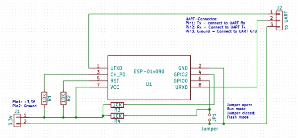
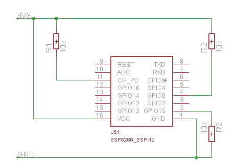
I've googled a lot to find a definitive wiring guide of the esp01 (not the 01s one) module for normal boot operations, and I can't find any good reference, just blog posts or forums discussions.
The best I've seen for the moment is at : https://www.letscontrolit.com/wiki/inde ... he_ESP8266

I see 4 x 10k pull up resistors: CH_PD, GPIO0, RST, GPIO2
According to my tests, only CH_PD + GPIO0 are needed to have the ESP to boot correctly. I've even connected CH_PD directly to VCC, because i saw this on many other sites.
Because i want to solder everything on the ESP itself, and also add a capacitor for power, the less components, the easier to solder...
(Imagine the mess with 4 resistors + 1 capacitor
1) Are RST and GPIO2 pullup resistors really needed, and why?
2) Is the resistor on CH_PD needed. Wiring vcc directly would be bad ?
3) Any advice on the capacitor between Gnd and Vcc? Thanks to the guide on the wiki, ia already bought some 10uF tantalum capacitor, just in case. Would they do the job correctly ? Are they really needed (knowing that the relay also have a 10uF capa, but on the 5V rail, just before the LD1117 regulator?
sorry is theses question seem dumb ...i'm a software guy
Thank you
