Two thinks dont work in my projekt. Is can see the Device Adress in the Device from DS18b20 overview but i can´t select the ID in the Senor settings.
I hace a LCD2004 configured. But i dobt´t understand how i can this wake Up over a separte Switch/Push. Enabled the sleep in Display and configured a Switch on D7. Have i do something in the configuration witch PullUps?
Thanks a lot
DS18b20 and Display Button
Moderators: grovkillen, Stuntteam, TD-er
Re: DS18b20 and Display Button
Just like in the screenshot posted in the documentation: https://espeasy.readthedocs.io/en/lates ... #p004-page
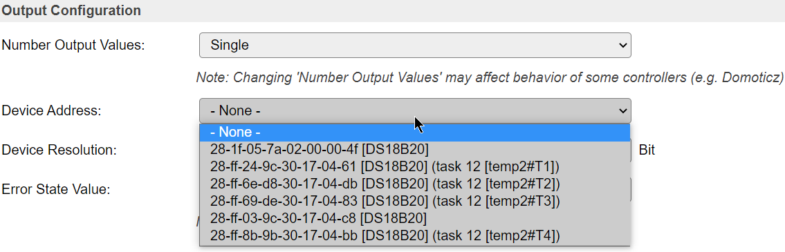
Does it show the items with a task mentioned next to the device adress?
Does it show the items with a task mentioned next to the device adress?
Re: DS18b20 and Display Button
No ther ist no device Adress in the DropDown Box
Re: DS18b20 and Display Button
Do you have a pull-up resistor present?
In the web interface ESPEasy does perform a new scan when opening the page.
But maybe it cannot read it well each time?
But to be honest, I am afraid I might not understand the actual problem you're seeing.
So maybe you can explain it a bit more?
For example, which pin are you using?
Which build of ESPEasy?
Running on ESP8266 or ESP32?
Re: DS18b20 and Display Button
Thanks for your patience. Yes I used a PulUp Resistor. Now i used not mor the D%. I changed to D3. And its works. I don´t no why but ist works 
I used an ESP3266 Wemos D1.
I used an ESP3266 Wemos D1.
Re: DS18b20 and Display Button
See also this section of the documentation: https://espeasy.readthedocs.io/en/lates ... on-esp8266
Assuming you meant "D5", which is GPIO14. (this D-notation once introduced is absolutely confusing, so please refer to GPIO nrs)
GPIO14 should be fine to use for this.
Given it is now working with GPIO-0 (D3), I think your pull-up resistor may not be sufficient.
GPIO-0 does have a pull-up resistor as it is needed to boot the ESP into running the sketch.
If it is pulled down at boot, the ESP will enter flash mode.
Re: DS18b20 and Display Button
Now the sensors work. But the display wakeup don´t work.
I selected the D7 (GPIO 13) in the Dispaly konfiguration. Sleep Time 60 sec. But when ich close GND to D7 the display do not wake up
I selected the D7 (GPIO 13) in the Dispaly konfiguration. Sleep Time 60 sec. But when ich close GND to D7 the display do not wake up
Re: DS18b20 and Display Button
Can you see what the state of this pin is before closing the connection to GND?
Not all pins are pulled-up by a resistor.
So maybe you should add a pull-up resistor between this pin and 3V3?
The actual resistor-value doesn't matter much. Something between 4k7 and 22k would be fine.
Most pull-up resistors used in ESP boards are about 10k or 12k.
Another thing you could try is to enable the internal pull-up resistor on the hardware tab under "GPIO boot states"
This isn't a very strong pull-up (typically 50k-80k) but for testing this theory it will be fine.
When you're using a longer cable to this button/switch, you should use a stronger pull-up resistor.
Who is online
Users browsing this forum: No registered users and 13 guests