Difference between revisions of "User:Shardan/Dustsensor GP2Y10"
(First publish) |
|||
| (2 intermediate revisions by the same user not shown) | |||
| Line 26: | Line 26: | ||
=Schematics= | =Schematics= | ||
| − | [ | + | [[File:User-Shardan Dustsensor-Schematic Pic.jpg]] |
Don’t worry: It looks more complex than it is. We will walk through the parts and explain. | Don’t worry: It looks more complex than it is. We will walk through the parts and explain. | ||
| Line 79: | Line 79: | ||
=PCB= | =PCB= | ||
| − | [ | + | [[File:User-Shardan Dustsensor-Layout.jpg|500px]] <br /> |
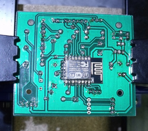
This single side PCB is kept simple, it should be possible to etch it at home. All parts are mounted | This single side PCB is kept simple, it should be possible to etch it at home. All parts are mounted | ||
from the front side “trough hole”.<br /> | from the front side “trough hole”.<br /> | ||
| Line 87: | Line 87: | ||
Within the PDF's a 1:1 printout is provided for etching. | Within the PDF's a 1:1 printout is provided for etching. | ||
| − | The fully populated PCB – component side | + | The fully populated PCB – component side <br /> |
| − | [ | + | [[File:EnviroSensor PCB Parts.jpg|500px]]<br /> |
| − | …and bottom (soldering) side. | + | …and bottom (soldering) side.<br /> |
| − | [ | + | [[File:EnviroSensor PCB Solder.jpg|500 px]]<br /> |
=Case= | =Case= | ||
I’ve used a standard case from market. It is sold under several brand names, in fact you may find it | I’ve used a standard case from market. It is sold under several brand names, in fact you may find it | ||
even on Aliexpress or at many electronics providers. I’ve got it here: | even on Aliexpress or at many electronics providers. I’ve got it here: | ||
| − | https://www.reichelt.de/Kunststoff-Kleingehaeuse/EUROBOXSW/ | + | [https://www.reichelt.de/Kunststoff-Kleingehaeuse/EUROBOXSW/3/index.html?ACTION=3&GROUPID=7715&ARTICLE=50429&SHOW=0&START=0&OFFSET=50&SID=94WeyucKwQATMAABkE9hodf3b921f5ffd24e8964d4dcc85ff2abf&LANGUAGE=EN] <br /> |
| − | 3/index.html?ACTION=3&GROUPID=7715&ARTICLE=50429&SHOW=0&START=0&OFFSET=50& | ||
| − | |||
The PCB is developed to fit into this case including sensor, fan and display. | The PCB is developed to fit into this case including sensor, fan and display. | ||
You may use other cases but you will have to drill mounting holes for the PCB.<br /> | You may use other cases but you will have to drill mounting holes for the PCB.<br /> | ||
| − | [ | + | [[File:GP2Y10 mounted in Case.jpg|500 px]] |
Mounting the PCB, Sensor and fan together with display in the case. | Mounting the PCB, Sensor and fan together with display in the case. | ||
| Line 145: | Line 143: | ||
Set your devices as shown here. If you use a BMP-180 or BMP-280 change settings accordingly.<br /> | Set your devices as shown here. If you use a BMP-180 or BMP-280 change settings accordingly.<br /> | ||
Settings for the GP2Y10:<br /> | Settings for the GP2Y10:<br /> | ||
| − | [ | + | [[File:User-Shardan Dustsensor-Setting GP2Y10.jpg|500 px]] |
<br /> | <br /> | ||
Settings for the SI7021 (Change accordingly for BMP-types):<br /> | Settings for the SI7021 (Change accordingly for BMP-types):<br /> | ||
| − | [ | + | [[File:User-Shardan Dustsensor-Setting SI7021.jpg|500 px]] |
<br /> | <br /> | ||
| − | Settings for the display (If you use one at all, it is optional): | + | Settings for the display (If you use one at all, it is optional):<br /> |
| − | [ | + | [[File:User-Shardan Dustsensor-Setting Display.jpg]] |
<br /> | <br /> | ||
| − | If all settings are done, your device list should look similar to this: | + | If all settings are done, your device list should look similar to this:<br /> |
| − | [ | + | [[File:User-Shardan Dustsensor-Setting DEviceList.jpg|500 px]] |
<br /> | <br /> | ||
Congratulations, the sensor itself is up and running.<br /> | Congratulations, the sensor itself is up and running.<br /> | ||
| Line 221: | Line 219: | ||
That’s all, folks. | That’s all, folks. | ||
Have fun with your dust sensor. | Have fun with your dust sensor. | ||
| + | |||
| + | =Files= | ||
| + | [[File:User-Shardan Dustsensor Documentation wPCB.pdf]]<br/> | ||
| + | [[File:User-Shardan Dustsensor-Schematics.pdf]]<br /> | ||
| + | [[File:User-Shardan Dustsensor PCB.pdf]]<BR /> | ||
Latest revision as of 21:52, 29 October 2017
Contents
Dust Sensor using GP2Y10
Dust sensors detect fine dust (“aerosol”) floating in the air. They are used to determine air quality indoor and outdoor.
Limits of the GP2Y10
The GP2Y10 sensor was developed to give a general value of the air quality. The sensor is originally used to control air cleaners so it’s capabilities are limited. It is not able to differentiate between dust sizes, e. g. PM2.5 and PM10. So the sensor device can give a relative value for air quality rating. You won’t get a value “xx μg/m³”.
How Does the Sensor Work?
If you ever have used a pocket light in the dark you may have noticed floating dust in the light beam. This is basically the way these sensors work. Inside the sensor box is a dark chamber. A LED flashes inside the chamber, a photo transistor detects the light reflected by the dust. A small circuit converts the measurement into an analog voltage.
Prerequisites
The circuit needs an external 5V power supply. Do not use a cheap power supply. It should give a reliable power of 1 … 1.5 A at least. This circuit uses standard trough-hole parts so it is relatively simple to build.
Schematics
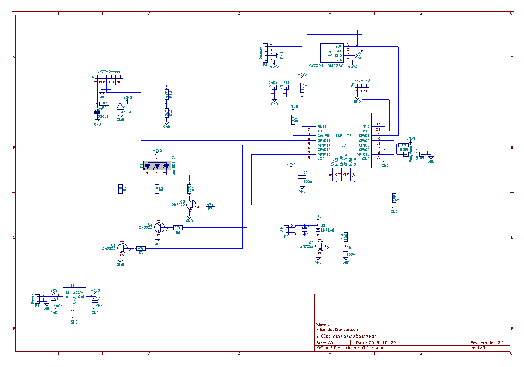
Don’t worry: It looks more complex than it is. We will walk through the parts and explain.
You may print a full sized schematics, it is provided with the PDFs.
Starting at the bottom left you see the voltage regulator, a LF-33 (U1). Together with the capacitors
C1 and C2 it provides the 3.3V for the ESP-12E/F. P6 is the connector to the external power supply.
P1 on the top left connects to the GP2Y10. The pins use the same order as the pins at the GP2Y10 so
connecting is done easily.
C3, C5 and R4 make a filter for the LED pulses to keep voltage spikes off from the other parts.
R10 and R13 divide the output voltage down to a level the ESP can take. This is
necessary as the GP2Y10 can give back around 3 volts, the analog input of the ESP can take up to 1
volt.
The indicator LED D1 is a RGB LED with common anode. It shows a raw indicator of air quality by
colors: Blue – cyan – green – yellow – Red (From good to bad). The transistors Q1,Q2 and Q3 provide
a bit more power for the LED as the GPIO’s of the ESP alone can give. R1, R2 and R3 are for limiting
the LED current. R5, R6 and R7 are the basis resistors for driving the transistors.
The transistor Q4 has a special function.
The GP2Y10 has no internal fan. To get enough air from the environment into the sensor it needs an
external fan. These little fans are noisy, this might be disturbing for example in the night at the
sleeping room. You may use Q4 / GPIO10 to switch off the fan at night times.
It is even possible to turn the fan into slower rotation by using PWM on GPIO10. But the small fans
tend to “whistle” if driven by PWM so I don’t recommend that. Use a 12…15 Ohm resistor in the fan
cable to turn it down instead.
D2 is a wheeling diode to keep off high voltage spikes from the motor coils. This should be
implemented inside the fan already, but who knows with the cheap fans offered on the market?
C7 is optional. It might be necessary to keep “humming” from the voltage supply with some fans.
Try values from 2,2 … 10 μF if necessary.
On the top right you see the connector P2. It can be used to connect a SSD1306 OLED display.
Besides P6 you see a sensor, a BMP-280, BMP-180 or SI7021 can be used (“Thumbnail” size
breakout).
P8 gives the Reset pin of the ESP-12E/F. Shorting to ground (P3) resets the ESP.
P5 shorted to ground (P7) sets the ESP into flash mode.
P4 provides the serial interface for your flash progging adapter.
So only the ESP-circuit itself is left.
You may use: ESP-12, ESP-12E and ESP-12F. IF you want to use an external antenna you may also use
the ESP-07S which is an ESP-12 with an IPEX plug instead of an antenna. It has 4MB as the ESP-12
has.
C4 is a ceramic type capacitor to block high frequency generated by the ESP. Do not use film
capacitors here, they are not suitable for this purpose.
R8, R9, R11 and R12 are the necessary pull-up / pull-down resistors the ESP needs to set the standard running mode.
PCB
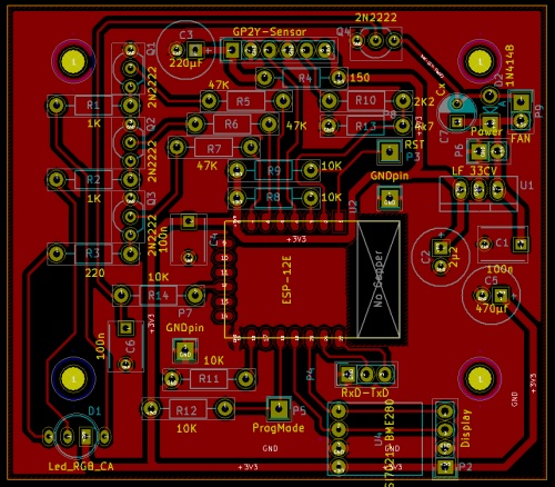
This single side PCB is kept simple, it should be possible to etch it at home. All parts are mounted
from the front side “trough hole”.
Only the ESP is mounted on the bottom side of the PCB.
Within the PDF's a 1:1 printout is provided for etching.
The fully populated PCB – component side
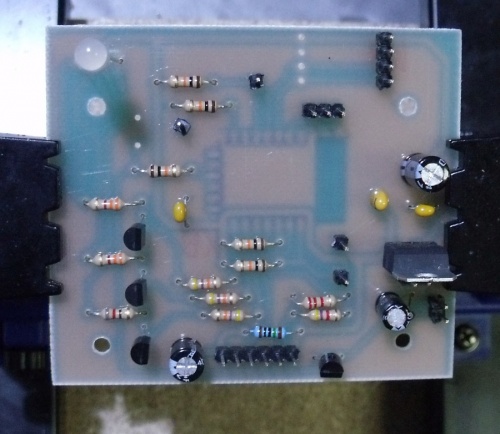
…and bottom (soldering) side.
Case
I’ve used a standard case from market. It is sold under several brand names, in fact you may find it
even on Aliexpress or at many electronics providers. I’ve got it here:
[1]
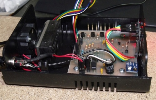
The PCB is developed to fit into this case including sensor, fan and display.
You may use other cases but you will have to drill mounting holes for the PCB.
Mounting the PCB, Sensor and fan together with display in the case. The sensor was fixed with a double sided adhesive tape.
Building the Circuit
As we use though hole components this device do not need too much experience with soldering. A
standard soldering iron for electronics will do for most parts. Only the ESP needs a pencil tip type
iron.
Be very carefull with soldering the ESP-12.
The solder tends to creep under the ESP-chip short circuiting some pins.
I recommend to solder one single pin of the ESP and then check:
- Is it correctly aligned to the pcb?
- Is it really flat on the pcb or is there some “air” between pcb and chip?
If you solder just one pin first, these things are correctable.
A completely soldered ESP-12 is fixed. It is somewhat difficult to de-solder it, often the pcb and/or
the chip get damaged.
Place resistors first, then capacitors and pin headers. The transistors and the LF-33 voltage regulator
follow, and at last the ESP from the bottom side.
Before you power up first time, please check very carefully:
  - Any bad soldering points?
  - Any unwanted soldering bridges between solder points?
A steel needle or a sharp cutter knife are helpful here.
Flashing
  - Connect your programming adapter to the “serial” pins.
  - Shorten the pins P5 and P7 to set flash mode.
  - Start flashing in your flash tool and shorten P3-P8 for a short moment.
  - Wait until flashing succeded.
  - Switch off the device.
  - Disconnect the adapter.
  - disconnect P5-P7
Done, that’s it.
ESPEasy Settings
Set your devices as shown here. If you use a BMP-180 or BMP-280 change settings accordingly.
Settings for the GP2Y10:
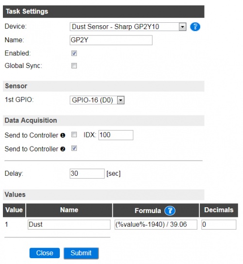
Settings for the SI7021 (Change accordingly for BMP-types):
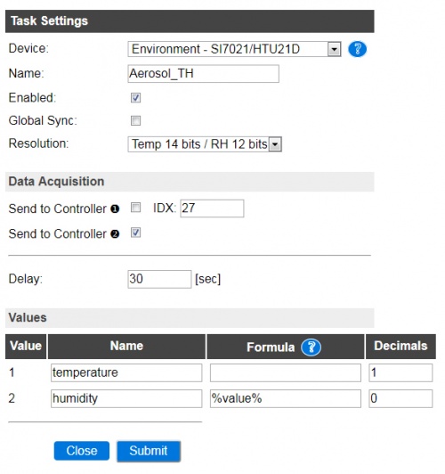
Settings for the display (If you use one at all, it is optional):
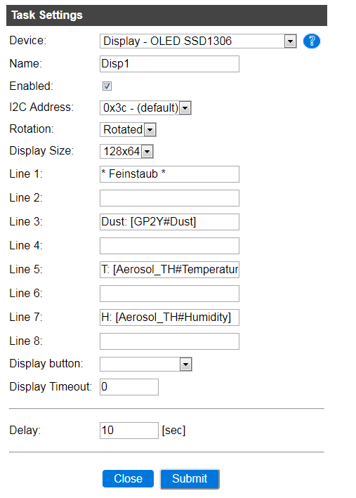
If all settings are done, your device list should look similar to this:

Congratulations, the sensor itself is up and running.
Getting LED and Fan to Work - Rules
The LED should show a color depending to the amount of dust the sensor detects.
For now the fan should be switched on when powering on the device.
For this a simple rule does the job:
 On System#Boot do
    gpio,10,1
 endon
This just sets GPIO10 to “1” on system boot
The Rules for LED need a bit of explanation.
As the PCB is developed the LED is connected to these GPIO’S:
 GPIO12 = Green
 GPIO13 = Blue
 GPIO14 = Red
So we simply could say:
 On a dust value below 25 switch GPIO13 on, otherwise off
 On a dust value of 26…50 switch GPIO12 on, otherwise off
and so on.
But this would give just blue, green and red with an additional rule.
We left out cyan and yellow! What to do?
It’s simple: We define some overlapping between the colors.
 Below 25: Blue
 26….40 Cyan
 41….50 Green
 51….75 Yellow
 75….330 Red
So with this definition the Blue led should be “on” from 0….40, as cyan is mixed from blue and green.
Green should be on from 26 …. 75 as we need it for cyan, green and yellow (red/green mix).
Please note: These values are just what I use. You may adapt it to your needs.
If you check the rules aou may notice an extra rule for values >330.
This switches off the LED on values out of the limits of the sensor and analog input.
A nice (and honestly not planned) side effect: If out of limits the LED flashes every some seconds shortly showing you’re out of range.
So let’s see a complete set of rules for fan and LED:
 On System#Boot do
   gpio,10,1
 endon
 on GP2Y#Dust do
   if [GP2Y#Dust] > 40
     gpio,13,0
   else
     gpio,13,1
   endif
   if [GP2Y#Dust] >25
     gpio,12,1
   else
     gpio,12,0
   endif
   if [GP2Y#Dust] > 75
     gpio,12,0
   endif
   if [GP2Y#Dust] > 50
     gpio,14,1
   else
     gpio,14,0
   endif
   if [GP2Y#Dust] > 330
     gpio,12,0
     gpio,13,0
     gpio,14,0
   endif
 endon
That’s all, folks. Have fun with your dust sensor.
Files
File:User-Shardan Dustsensor Documentation wPCB.pdf
File:User-Shardan Dustsensor-Schematics.pdf
File:User-Shardan Dustsensor PCB.pdf
