Difference between revisions of "Sonoff DIY 1ch"
Jump to navigation
Jump to search
Grovkillen (talk | contribs) |
Grovkillen (talk | contribs) |
||
| Line 12: | Line 12: | ||
* GPIO's broken out/available to free use: None | * GPIO's broken out/available to free use: None | ||
* GPIO tied to onboard hardware: 12 (Relay 10A@230VAC), 13 (LED red) | * GPIO tied to onboard hardware: 12 (Relay 10A@230VAC), 13 (LED red) | ||
| − | * Power supply information: | + | * Power supply information: 5VDC (USB or wire in) |
* Antenna: onboard PCB antenna | * Antenna: onboard PCB antenna | ||
Revision as of 23:05, 2 December 2017
Introduction
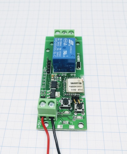
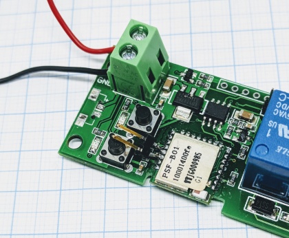
The Sonoff DIY 1ch is a relay unit. It is based on the ESP8285 chip and can control one relay.
Hardware
- ESP chip version: ESP8285
- Flash size: 1M
- Onboard USB-TTL converter: No
- GPIO's broken out/available to free use: None
- GPIO tied to onboard hardware: 12 (Relay 10A@230VAC), 13 (LED red)
- Power supply information: 5VDC (USB or wire in)
- Antenna: onboard PCB antenna
Wiring/flashing
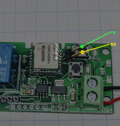
A programmer is needed to flash this device.
  Programmer     ESP
  TX      <-->   RX (fourth pin seen in picture above)
  RX      <-->   TX (third pin seen in picture above)

  Power
  5V    <-->   VCC (input power, also usb can be used)
  GND     <-->   GND (input power)
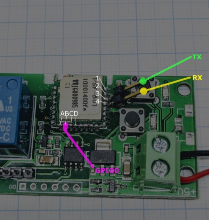
In order to get the unit in flash mode the GPIO-0 needs to be LOW. You find GPIO-0 on the second pin (marked "B" in picture below). Connect that pin to GND.


