Difference between revisions of "Devices"
Jump to navigation
Jump to search
| (76 intermediate revisions by 8 users not shown) | |||
| Line 1: | Line 1: | ||
| + | == Up-to-date list == | ||
| + | '''Warning''' | ||
| + | This is an outdated list, please see the up to date list on [https://espeasy.readthedocs.io/en/latest/Plugin/_Plugin.html ReadTheDocs - Plugins] | ||
| + | |||
| + | |||
| + | == Devices == | ||
{| class="wikitable mw-collapsible sortable" | {| class="wikitable mw-collapsible sortable" | ||
| Line 15: | Line 21: | ||
|- | |- | ||
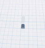
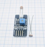
| − | | | + | | Pulse counter |
| [[File:TCR5000.jpg|thumb|upright=0.5|center|link=TCR5000|[[TCR5000]]]] | | [[File:TCR5000.jpg|thumb|upright=0.5|center|link=TCR5000|[[TCR5000]]]] | ||
| IR emitter + phototransistor (for ex. water/electricity meters), distance | | IR emitter + phototransistor (for ex. water/electricity meters), distance | ||
| Line 27: | Line 33: | ||
|- | |- | ||
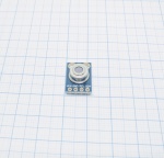
| − | | | + | | Environment |
| [[File:DS18b20.jpg|thumb|upright=0.5|center|link=Dallas_DS18b20|[[Dallas_DS18b20 | DS18b20]] ]] | | [[File:DS18b20.jpg|thumb|upright=0.5|center|link=Dallas_DS18b20|[[Dallas_DS18b20 | DS18b20]] ]] | ||
| Temperature (-55 to +125°C) | | Temperature (-55 to +125°C) | ||
| Line 39: | Line 45: | ||
|- | |- | ||
| − | | | + | | Environment |
| [[File:MLX90614.jpg|thumb|upright=0.5|center|link=MLX90614|[[MLX90614]]]] | | [[File:MLX90614.jpg|thumb|upright=0.5|center|link=MLX90614|[[MLX90614]]]] | ||
| Sensor temperature (-40 to +125°C) | | Sensor temperature (-40 to +125°C) | ||
| Line 65: | Line 71: | ||
|- | |- | ||
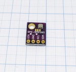
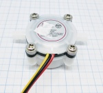
| − | + | | Environment | |
| − | | | + | | [[File:BME280 new.jpg|thumb|upright=0.5|center|link=BME280|[[BME280]]]] |
| temperature (-40 to +85°C) | | temperature (-40 to +85°C) | ||
humidity ( 0…100 % rel. humidity) | humidity ( 0…100 % rel. humidity) | ||
barometric pressure (300-1100 hPa) | barometric pressure (300-1100 hPa) | ||
| − | | | + | | 1.8 - 5V |
| SDA/SCL or 2 digital GPIO | | SDA/SCL or 2 digital GPIO | ||
| I²C bus | | I²C bus | ||
| Line 107: | Line 113: | ||
|- | |- | ||
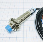
| − | | | + | | Pulse counter |
| − | | | + | | [[File:LJ12A3_new.jpg|thumb|upright=0.5|center|link=LJ12A3|[[LJ12A3]]]] |
| Inductive proximity sensor | | Inductive proximity sensor | ||
| 5V - 12V | | 5V - 12V | ||
| Line 119: | Line 125: | ||
|- | |- | ||
| − | | | + | | Pulse counter |
| [[File:Flow_sensor_pulse.jpg|thumb|upright=0.5|center|link=Pulse logic input|[[Pulse logic input]]]] | | [[File:Flow_sensor_pulse.jpg|thumb|upright=0.5|center|link=Pulse logic input|[[Pulse logic input]]]] | ||
| General, output as pulse | | General, output as pulse | ||
| Line 131: | Line 137: | ||
|- | |- | ||
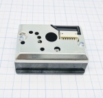
| − | | | + | | Dust |
| [[File:GP2Y10.jpg|thumb|upright=0.5|center|link=GP2Y10|[[GP2Y10]] ]] | | [[File:GP2Y10.jpg|thumb|upright=0.5|center|link=GP2Y10|[[GP2Y10]] ]] | ||
| "Dust" (particle matter: PM2.5) | | "Dust" (particle matter: PM2.5) | ||
| − | | 5V | + | | 3,3V(5V) |
| 1 analog (data) and 1 digital GPIO (for LED) | | 1 analog (data) and 1 digital GPIO (for LED) | ||
| analog (for data) | | analog (for data) | ||
| N/A | | N/A | ||
| − | | no | + | | 3,3V:no 5V:Needs special adaption |
| Small flanges on the sides | | Small flanges on the sides | ||
| 46.0mm x 30.0mm x 17.6mm | | 46.0mm x 30.0mm x 17.6mm | ||
| + | |- | ||
| + | |||
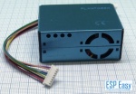
| + | | Dust | ||
| + | | [[File:PMS5003 2.jpg|thumb|upright=0.5|center|link=PMSx003|[[PMSx003]] ]] | ||
| + | | "Dust" (particle matter: PM1/2.5/10) | ||
| + | | 5V | ||
| + | | 4 digital GPIO | ||
| + | | serial | ||
| + | | N/A | ||
| + | | No | ||
| + | | | ||
| + | | | ||
|- | |- | ||
| Line 155: | Line 173: | ||
|- | |- | ||
| − | | | + | | Environment |
| [["Soil_moisture_sensor" | Soil moisture sensor]] [[File:Soilmoisturesensor_small.jpg|link="Soil_moisture_sensor"]] | | [["Soil_moisture_sensor" | Soil moisture sensor]] [[File:Soilmoisturesensor_small.jpg|link="Soil_moisture_sensor"]] | ||
| capacitive moisture, temperature, light | | capacitive moisture, temperature, light | ||
| Line 167: | Line 185: | ||
|- | |- | ||
| − | | | + | | Gases |
| [["CO2_Sensor_MH-Z19" | MH-Z19]] [[File:mh-z19.jpg|100px|link="CO2_Sensor_MH-Z19"]] | | [["CO2_Sensor_MH-Z19" | MH-Z19]] [[File:mh-z19.jpg|100px|link="CO2_Sensor_MH-Z19"]] | ||
| CO2 ppm, temperature, U | | CO2 ppm, temperature, U | ||
| − | | | + | | 5V |
| 2 digital GPIO (Software-Serial) | | 2 digital GPIO (Software-Serial) | ||
| serial | | serial | ||
| Line 228: | Line 246: | ||
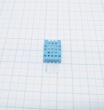
| Environment | | Environment | ||
| − | | [[File:DHT11.jpg|thumb|upright=0.5|center|link=DHT11_DHT22|[[DHT11_DHT22 | DHT11 (DHT22 | + | | [[File:DHT11.jpg|thumb|upright=0.5|center|link=DHT11_DHT22|[[DHT11_DHT22 | DHT11]]]] |
| + | | temperature (-40 to +85°C) | ||
| + | humidity ( 0…100 % rel. humidity) | ||
| + | | 3.3V - 5V | ||
| + | | 1 digital GPIO for multiple sensors | ||
| + | | 1wire bus | ||
| + | | N/A | ||
| + | | no | ||
| + | | Ø? hole (DHT11) | ||
| + | | ? | ||
| + | |- | ||
| + | |||
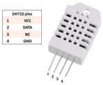
| + | | Environment | ||
| + | | [[File:DHT22.png|thumb|upright=0.5|center|link=DHT11_DHT22|[[DHT11_DHT22 | DHT22]]]] | ||
| temperature (-40 to +85°C) | | temperature (-40 to +85°C) | ||
humidity ( 0…100 % rel. humidity) | humidity ( 0…100 % rel. humidity) | ||
| Line 254: | Line 285: | ||
|- | |- | ||
| − | + | | Environment | |
| [[SI7021/HTU21D| SI7021/HTU21D]] [[File:SI7021.png|100px|link=SI7021/HTU21D]] | | [[SI7021/HTU21D| SI7021/HTU21D]] [[File:SI7021.png|100px|link=SI7021/HTU21D]] | ||
| temperature (-40 to +125°C) | | temperature (-40 to +125°C) | ||
| Line 267: | Line 298: | ||
|- | |- | ||
| − | + | | Environment | |
| [[SHT1X | SHT1X]] [[File:SHT1X.png|100px|link=SHT1X]] | | [[SHT1X | SHT1X]] [[File:SHT1X.png|100px|link=SHT1X]] | ||
| temperature | | temperature | ||
humidity | humidity | ||
| 3.3V - 5V | | 3.3V - 5V | ||
| − | | | + | | 2 digital GPIO |
| − | | | + | | no |
| − | | | + | | n/a |
| no | | no | ||
| | | | ||
| Line 280: | Line 311: | ||
|- | |- | ||
| − | + | | Environment | |
| [[AM2320_i2c_Temperatur_and_Humidity_Sensor | AM2320 ]] [[File:AM2320-Sensor.jpg|100px|link=AM2320_i2c_Temperatur_and_Humidity_Sensor ]] | | [[AM2320_i2c_Temperatur_and_Humidity_Sensor | AM2320 ]] [[File:AM2320-Sensor.jpg|100px|link=AM2320_i2c_Temperatur_and_Humidity_Sensor ]] | ||
| temperature (-40 to +80°C) | | temperature (-40 to +80°C) | ||
| Line 293: | Line 324: | ||
|- | |- | ||
| − | + | | RFID | |
| [[Wiegand-26| Wiegand]] [[File:WiegandRFID_1.jpg|100px|link=Wiegand-26 ]] | | [[Wiegand-26| Wiegand]] [[File:WiegandRFID_1.jpg|100px|link=Wiegand-26 ]] | ||
| RFID | | RFID | ||
| Line 305: | Line 336: | ||
|- | |- | ||
| − | + | | RFID | |
| [[PN532 | PN532]] [[File:PN532.png|100px|link=PN532 ]] | | [[PN532 | PN532]] [[File:PN532.png|100px|link=PN532 ]] | ||
| RFID | | RFID | ||
| 3.3V | | 3.3V | ||
| − | | | + | | SDA/SCL or 2 digital GPIO |
| − | | | + | | I²C bus |
| | | | ||
| no | | no | ||
| Line 317: | Line 348: | ||
|- | |- | ||
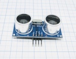
| − | + | | Distance | |
| − | | [[HC-SR04 | HC-SR04 | + | | [[File:HC-SR04.jpg|thumb|upright=0.5|center|link=HC-SR04|[[HC-SR04 | HC-SR04]]]] |
| Ultrasonic Distance sensor | | Ultrasonic Distance sensor | ||
| 5V | | 5V | ||
| + | | 2 digital GPIO (one for trigger, one for echo) | ||
| + | | no | ||
| + | | n/a | ||
| + | | yes | ||
| + | | | ||
| + | | | ||
| + | |- | ||
| + | |||
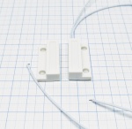
| + | | Switch input | ||
| + | | [[File:Lightswitch.jpg|thumb|upright=0.5|center|link=Switch|[[Switch|Switches]]]] | ||
| + | | Switch | ||
| + | | ? | ||
|? | |? | ||
| | | | ||
| | | | ||
| − | | | + | | ? |
| + | | | ||
| + | | | ||
| + | |- | ||
| + | |||
| + | | Switch input | ||
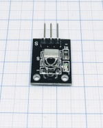
| + | | [[File:PIR.jpg|thumb|upright=0.5|center|link=PIR Sensor|[[PIR Sensor| PIR Sensor]]]] | ||
| + | | PIR Switch | ||
| + | | 5...12V | ||
| + | | 1 digital GPIO | ||
| + | | | ||
| + | | | ||
| + | | No (see text) | ||
| | | | ||
| | | | ||
|- | |- | ||
| − | | Switch | + | | Switch input |
| − | | | + | | [[File:DoorSwitchESPEasy.jpg|thumb|upright=0.5|center|link=Switch|[[Switch|Door Switch]]]] |
| − | | Switch | + | | Door Switch |
| ? | | ? | ||
|? | |? | ||
| Line 341: | Line 396: | ||
|- | |- | ||
| − | | | + | | Analog input |
| − | | | + | | [[File:Analog.png|thumb|upright=0.5|center|link=Analog|[[Analog|Analog signals]]]] |
| − | | | + | | Analog Input |
| ? | | ? | ||
|? | |? | ||
| Line 353: | Line 408: | ||
|- | |- | ||
| + | | Analog input | ||
| + | | [[File:PCF8591Module.jpg|thumb|upright=0.5|center|link=PCF8591|[[PCF8591| PCF8591]]]] | ||
| + | | Analog Input | ||
| + | | 3.3V - 5V | ||
| + | | SDA/SCL or 2 digital GPIO | ||
| + | | I²C bus | ||
| + | | 0x48 (changeable) | ||
| + | | no | ||
| + | | | ||
| + | | | ||
| + | |- | ||
| + | |||
| + | | Analog input | ||
| + | | [[File:ADS1115.jpg|thumb|upright=0.5|center|link=ADS1115|[[ADS1115 | ADS1115]]]] | ||
| + | | Analog Input | ||
| + | | 3.3V - 5V | ||
| + | | SDA/SCL or 2 digital GPIO | ||
| + | | I²C bus | ||
| + | | 0x48-0x4B | ||
| + | | no | ||
| + | | | ||
| + | | | ||
| + | |- | ||
| + | |||
| + | | Extra IO | ||
| + | | [[File:MCP23017DIP28.jpg|thumb|upright=0.5|center|link=MCP23017|[[MCP23017]]]] | ||
| + | | Input / output | ||
| + | | 3.3V | ||
| + | | SDA/SCL or 2 digital GPIO | ||
| + | | I²C bus | ||
| + | | 0x20-0x27 | ||
| + | | no | ||
| + | | | ||
| + | | | ||
| + | |- | ||
| + | |||
| + | | Communication | ||
| + | | [[File:IR reciever.jpg|thumb|upright=0.5|center|link=IR|[[IR|IR reciever]]]] | ||
| + | | IR | ||
| + | | 3,3V | ||
| + | | 1 digital GPIO | ||
| + | | no | ||
| + | | n/a | ||
| + | | no | ||
| + | | | ||
| + | | | ||
| + | |- | ||
| + | |||
| + | | Gyro | ||
| + | | [[MPU6050 | MPU 6050]] [[File:Mpu-6050.jpg|80px|link=MPU6050]] | ||
| + | | Motion | ||
| + | | 3.3V - 5V | ||
| + | | SDA/SCL or 2 digital GPIO | ||
| + | | I²C bus | ||
| + | | 0x68<br/>0x69 | ||
| + | | no | ||
| + | | | ||
| + | | | ||
| + | |- | ||
| + | |||
| + | | Gases | ||
| + | | [[File:S8_006.jpg|thumb|upright=0.5|center|link=S8|[[S8 | SenseAir S8]]]] | ||
| + | | CO2 (ppm) | ||
| + | | 5V<br/>(not over 5.2V!) | ||
| + | | 2 digital GPIO (Software-Serial) | ||
| + | | serial | ||
| + | | N/A | ||
| + | | no | ||
| + | | Pins (4x + 5x)<br/>C-C2.54mm | ||
| + | | 32mm x 19.5mm x 8.2mm | ||
| + | |- | ||
| + | |||
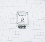
| + | | GPIO | ||
| + | | [[File:LED.jpg|thumb|upright=0.5|center|link=GPIO |[[GPIO | Output pin]]]] | ||
| + | | LED, tones, servos etc. | ||
| + | | 1.8V - 2.2V (max) | ||
| + | | 1 PWM GPIO | ||
| + | | - | ||
| + | | N/A | ||
| + | | no | ||
| + | | - | ||
| + | | - | ||
| + | |- | ||
| + | |||
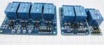
| + | | GPIO | ||
| + | | [[File:Relaisbordje.jpg|thumb|upright=0.5|center|link=Relais|[[Relais| Relays]]]] | ||
| + | | Relay | ||
| + | | 5V<br/>(3.3V - 5V Logic) | ||
| + | | 1 digital GPIO, per relay | ||
| + | | - | ||
| + | | N/A | ||
| + | | no | ||
| + | | - | ||
| + | | - | ||
| + | |- | ||
| + | |||
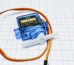
| + | | GPIO | ||
| + | | [[File:Servo motor.jpg|thumb|upright=0.5|center|link=Servo|[[Servo|Servo motor]]]] | ||
| + | | Output | ||
| + | | 3.3V - 12V (general) | ||
| + | | 1 digital GPIO, per servo | ||
| + | | - | ||
| + | | N/A | ||
| + | | no | ||
| + | | - | ||
| + | | - | ||
| + | |- | ||
| + | |||
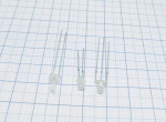
| + | | Communication | ||
| + | | [[File:IR transmitter.jpg|thumb|upright=0.5|center|link=IRTX|[[IRTX|IR transmitter]]]] | ||
| + | | Output | ||
| + | | 1V - 1.5V (general) | ||
| + | | 1 digital GPIO | ||
| + | | - | ||
| + | | N/A | ||
| + | | no | ||
| + | | - | ||
| + | | - | ||
| + | |- | ||
| + | |||
| + | | Extra IO | ||
| + | | [[PCF8574| PCF8574]] [[File:PCF8574.jpg|100px|link=PCF8574]] | ||
| + | | Input / output | ||
| + | | 2.5V - 6V | ||
| + | | SDA/SCL or 2 digital GPIO | ||
| + | | I²C bus | ||
| + | | 0x40-0x4F | ||
| + | | no | ||
| + | | - | ||
| + | | - | ||
| + | |- | ||
| + | |||
| + | | Extra IO | ||
| + | | [[PCA9685 | PCA9685 ]] [[File:PCA9685Module.jpg|100px|link=PCA9685]] | ||
| + | | Output | ||
| + | | 2.3V - 5.5V | ||
| + | | SDA/SCL or 2 digital GPIO | ||
| + | | I²C bus | ||
| + | | 0x40-0x7F | ||
| + | | no | ||
| + | | - | ||
| + | | - | ||
| + | |- | ||
| + | |||
| + | | Motor | ||
| + | | [["Adafruit_Motor_Shield_v2"| Adafruit Motor Shield v2]] [[File:Motor_shield_klein.jpg|100px|link="Adafruit_Motor_Shield_v2"]] | ||
| + | | Output | ||
| + | | 3.3V | ||
| + | | SDA/SCL or 2 digital GPIO | ||
| + | | I²C bus | ||
| + | | 0x60-0x80 | ||
| + | | no | ||
| + | | - | ||
| + | | - | ||
| + | |- | ||
| + | |||
| + | | Notify | ||
| + | | [[Buzzer (RTTL)| Buzzer]] [[File:buzzer.jpg|100px|link=Buzzer (RTTL)]] | ||
| + | | Output | ||
| + | | 3V - 5V (general) | ||
| + | | 1 digital GPIO | ||
| + | | - | ||
| + | | N/A | ||
| + | | no | ||
| + | | - | ||
| + | | - | ||
| + | |- | ||
| + | |||
| + | | Extra IO | ||
| + | | [[PWM GPIO| PWM GPIO (IRF520)]] [[File:MosFET.png|100px|link=PWM GPIO]] | ||
| + | | Output | ||
| + | | 3.3V or 5V | ||
| + | | 1 digital GPIO | ||
| + | | - | ||
| + | | N/A | ||
| + | | no | ||
| + | | - | ||
| + | | - | ||
| + | |- | ||
| + | |||
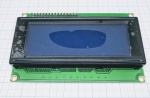
| + | | Display | ||
| + | | [[File:LCD display.jpg|thumb|upright=0.5|center|link=LCDDisplay|[[LCDDisplay|LCD display]]]] | ||
| + | | Output | ||
| + | | 5V (general) | ||
| + | | SDA/SCL or 2 digital GPIO | ||
| + | | I²C bus | ||
| + | | 0x27 | ||
| + | | no<br/>(yes if you use 5V logic and the ESP unit can't handle that voltage on GPIO) | ||
| + | | - | ||
| + | | - | ||
| + | |- | ||
| + | |||
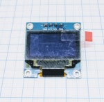
| + | | Display | ||
| + | | [[File:OLED display.jpg|thumb|upright=0.5|center|link=OLEDDisplay|[[OLEDDisplay|OLED display]]]] | ||
| + | | Output | ||
| + | | 3.3V or 5V (general) | ||
| + | | SDA/SCL or 2 digital GPIO | ||
| + | | I²C bus | ||
| + | | 0x3C | ||
| + | | no<br/>(yes if you use 5V logic and the ESP unit can't handle that voltage on GPIO) | ||
| + | | - | ||
| + | | - | ||
| + | |- | ||
| + | |||
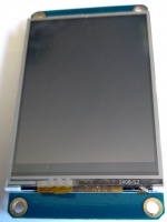
| + | | Display | ||
| + | | [[File:Nextion.jpg|thumb|upright=0.5|center|link=Plugin75|[[Plugin75|Nextion display]]]] | ||
| + | | Output | ||
| + | | 5V (general) | ||
| + | | Rx/Tx or 2 digital GPIO | ||
| + | | Serial | ||
| + | | N/A | ||
| + | | No<br/> The display outputs 3.2 volts max. | ||
| + | | 4 holes | ||
| + | | - | ||
| + | |- | ||
| + | |||
| + | | Generic | ||
| + | | [[File:Level_shifter_example.jpg|thumb|upright=0.5|center|link=Level Converter|[[Level Converter]]]] | ||
| + | | Level shifter (level converter) | ||
| + | | 3.3V - 5V | ||
| + | | Used inline with the wires. | ||
| + | | no | ||
| + | | N/A | ||
| + | | This is the level shifter, aka logic converter. Used to turn logics of higher voltage (5V) down to ESP friendly voltage (3.3V). | ||
| + | | - | ||
| + | | - | ||
| + | |- | ||
| + | |||
| + | | Notify | ||
| + | | [[File:DFPlayer-Mini-MP3-Player.jpg|thumb|upright=0.5|center|link=MP3 player|[[MP3 player|DFPlayer Mini]]]] | ||
| + | | MP3 player | ||
| + | | 3.3V - 5V | ||
| + | | 1 digital GPIO (TX) | ||
| + | | no | ||
| + | | N/A | ||
| + | | - | ||
| + | | - | ||
| + | | - | ||
| + | |- | ||
| + | |||
| + | | Notify | ||
| + | | [[File:YX5300-MP3-Player.jpg|thumb|upright=0.5|center|link=MP3 player|[[MP3 player|YX5300]]]] | ||
| + | | MP3 player | ||
| + | | 3.3V - 5V | ||
| + | | 1 digital GPIO (TX) | ||
| + | | no | ||
| + | | N/A | ||
| + | | - | ||
| + | | - | ||
| + | | - | ||
| + | |- | ||
| + | |||
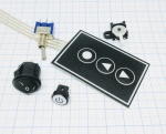
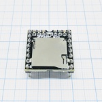
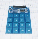
| + | | Keypad | ||
| + | | [[File:TTP229 1.jpg|thumb|upright=0.5|center|link=TTP229-B|[[TTP229-B]]]] | ||
| + | | Input | ||
| + | | 2.4V - 5.5V | ||
| + | | 2 digital GPIO | ||
| + | | NON-STANDARD<br>I²C bus | ||
| + | | N/A | ||
| + | | - | ||
| + | | Ø? (2x)<br/>C-C? | ||
| + | | - | ||
| + | |- | ||
| + | |||
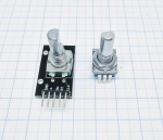
| + | | Switch input | ||
| + | | [[File:Rotary encoder 002.jpg|thumb|upright=0.5|center|link=Rotary_Encoder|[[Rotary Encoder]]]] | ||
| + | | Input | ||
| + | | 3.3V | ||
| + | | 2 digital GPIO<br/>3 GPIO if "0" is used | ||
| + | | no | ||
| + | | N/A | ||
| + | | - | ||
| + | | Ø? (2x)<br/>C-C? | ||
| + | | - | ||
| + | |- | ||
| + | |||
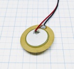
| + | | Notify | ||
| + | | [[File:Piezo_element.jpg|thumb|upright=0.5|center|link=Buzzer (RTTL)|[[Buzzer (RTTL)|Piezo element]]]] | ||
| + | | Output | ||
| + | | GPIO-power | ||
| + | | 1 digital GPIO | ||
| + | | - | ||
| + | | N/A | ||
| + | | no | ||
| + | | - | ||
| + | | - | ||
| + | |- | ||
| + | |||
| + | | Notify | ||
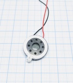
| + | | [[File:Small speaker.jpg|thumb|upright=0.5|center|link=Buzzer (RTTL)|[[Buzzer (RTTL)|Speaker]]]] | ||
| + | | Output | ||
| + | | GPIO-power | ||
| + | | 1 digital GPIO | ||
| + | | - | ||
| + | | N/A | ||
| + | | no | ||
| + | | - | ||
| + | | - | ||
| + | |- | ||
| + | |||
| + | | Display | ||
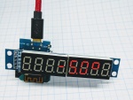
| + | | [[File:7D-display-001.jpg|thumb|upright=0.5|center|link=7 segment display|[[7 segment display|7 Segment Display]]]] | ||
| + | | Output | ||
| + | | 3.3V - 5V | ||
| + | | 2-3 digital GPIO | ||
| + | | - | ||
| + | | N/A | ||
| + | | no | ||
| + | | - | ||
| + | | - | ||
| + | |- | ||
|} | |} | ||
Latest revision as of 20:35, 18 November 2020
Up-to-date list
Warning This is an outdated list, please see the up to date list on ReadTheDocs - Plugins
Devices
| Device Type | Device Name | Physical values measured | Power In | connection method | output format | possible I²C addresses | level shifter required | mounting options | Size (LxWxH) |
|---|---|---|---|---|---|---|---|---|---|
| Pulse counter | IR emitter + phototransistor (for ex. water/electricity meters), distance | 3.3V - 5V | 1 digital GPIO (for pulse/proxy) and/or 1 Analog input (distance) | binary(0/1) (for pulse/proxy)/ 0-3.3V (distance) | N/A | no | Ø? (1x or 2x) C-C? |
||
| Environment | Temperature (-55 to +125°C) | 3.3V - 5V | 1 digital GPIO for multiple sensors | 1wire bus | N/A | no (yes if you use 5V logic and the ESP unit can't handle that voltage on GPIO) |
None but could be placed in a metal "pipe"/protective sleeve | Ø4.6mm x L4.6mm | |
| Environment | Sensor temperature (-40 to +125°C)
IR temperature (-70 to +380°C) |
3.3V - 5V | SDA/SCL or 2 digital GPIO | I²C bus | 0x5a | no | Ø? (2x) C-C? |
||
| Environment | BMP085/BMP180 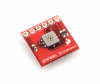
|
temperature (-40 to +85°C)
barometric pressure (300-1100 hPa) |
3.3V | SDA/SCL or 2 digital GPIO | I²C bus | 0x77 | no | Pins (6x) C-C2.54mm |
|
| Environment | temperature (-40 to +85°C)
humidity ( 0…100 % rel. humidity) barometric pressure (300-1100 hPa) |
1.8 - 5V | SDA/SCL or 2 digital GPIO | I²C bus | 0x76 0x77 |
no | Ø? (1x) | 19.0mm x 18.0mm x 3.0mm | |
| Environment | BMP280 
|
temperature (-40 to +85°C)
barometric pressure (300-1100 hPa) |
3.3V | SDA/SCL or 2 digital GPIO | I²C bus | 0x76 | no | Ø? (2x) C-C? |
19.0mm x 18.0mm x 3.0mm |
| Environment | MS5611 
|
temperature (-40 to +85°C)
barometric pressure (10 to 1200 mbar) |
3.3V | SDA/SCL or 2 digital GPIO | I²C bus | 0x76 | no | Ø? (2x) C-C? |
19.0mm x 18.0mm x 3.0mm |
| Pulse counter | Inductive proximity sensor | 5V - 12V | 1 digital GPIO (for pulse/proxy) | binary(0/1) (for pulse/proxy) | N/A | no (yes if you consider pull-up and pull-down resistors as level shifter?) |
M12 thread | Ø12mm x L55mm | |
| Pulse counter | General, output as pulse | 5V - 12V (in general) | 1 digital GPIO (for pulse) | binary(0/1) (for pulse) | N/A | no | |||
| Dust | "Dust" (particle matter: PM2.5) | 3,3V(5V) | 1 analog (data) and 1 digital GPIO (for LED) | analog (for data) | N/A | 3,3V:no 5V:Needs special adaption | Small flanges on the sides | 46.0mm x 30.0mm x 17.6mm | |
| Dust | "Dust" (particle matter: PM1/2.5/10) | 5V | 4 digital GPIO | serial | N/A | No | |||
| Current | Current (max ±3.2A), Voltage (max. 26V) | 3.3V - 5V | SDA/SCL or 2 digital GPIO | I²C bus | 0x40 0x41 0x44 0x45 |
no | Ø? holes (4x) C-C?? C-C?? |
? | |
| Environment | Soil moisture sensor 
|
capacitive moisture, temperature, light | 3.3V - 5V | SDA/SCL or 2 digital GPIO | I²C bus | 0x20 (changeable) | no | ? | ? |
| Gases | MH-Z19 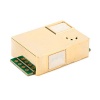
|
CO2 ppm, temperature, U | 5V | 2 digital GPIO (Software-Serial) | serial | N/A | no | Pins (4x + 5x) C-C2.54mm |
? |
| Light/Lux | BH1750 
|
Illuminance, Lux | 3.3V | SDA/SCL | I²C bus | 0x5c 0x23 |
no | Ø? holes (2x) C-C?? |
? |
| Light/Lux | TSL2561 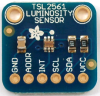
|
Illuminance, Lux | 3.3V | SDA/SCL | I²C bus | 0x29 0x39 0x49 |
no | Ø? holes (2x) C-C?? |
? |
| Light/Lux | RGB Color | 3.3V | SDA/SCL | I²C bus | 0x29 | no | Ø? holes (2x) C-C?? |
? | |
| Light/Lux | Light intensity Analog 1-100% or Binary above/below trigger value |
3.3V - 5V | 1 analog and/or 1 digital |
analog (0-3.3V) and/or binary (0/1) |
N/A | no | Ø? hole | ? | |
| Environment | temperature (-40 to +85°C)
humidity ( 0…100 % rel. humidity) |
3.3V - 5V | 1 digital GPIO for multiple sensors | 1wire bus | N/A | no | Ø? hole (DHT11) | ? | |
| Environment | temperature (-40 to +85°C)
humidity ( 0…100 % rel. humidity) |
3.3V - 5V | 1 digital GPIO for multiple sensors | 1wire bus | N/A | no | Ø? hole (DHT22) | ? | |
| Environment | DHT12 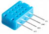
|
temperature (-20 to +60°C)
humidity ( 20…95 % rel. humidity) |
3.3V - 5V | 1 digital GPIO for multiple sensors | I²C bus (or 1wire bus) |
0xb8 | no | no | 12.3mm x 7.5mm x 4.7mm |
| Environment | SI7021/HTU21D 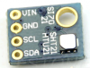
|
temperature (-40 to +125°C)
humidity ( 0…100 % rel. humidity) |
3.3V | SDA/SCL or 2 digital GPIO | I²C bus | 0x40 | no | ||
| Environment | SHT1X 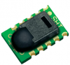
|
temperature
humidity |
3.3V - 5V | 2 digital GPIO | no | n/a | no | ||
| Environment | AM2320 
|
temperature (-40 to +80°C)
humidity ( 0…99.9 % rel. humidity) |
3.3V - 5V | SDA/SCL or 2 digital GPIO | I²C bus | 0x5C (not found via i2c scan?) | no | ||
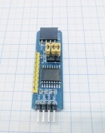
| RFID | Wiegand 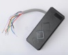
|
RFID | 6V - 12V | 2 digital GPIO | yes | ||||
| RFID | PN532 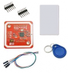
|
RFID | 3.3V | SDA/SCL or 2 digital GPIO | I²C bus | no | |||
| Distance | Ultrasonic Distance sensor | 5V | 2 digital GPIO (one for trigger, one for echo) | no | n/a | yes | |||
| Switch input | Switch | ? | ? | ? | |||||
| Switch input | PIR Switch | 5...12V | 1 digital GPIO | No (see text) | |||||
| Switch input | Door Switch | ? | ? | ? | |||||
| Analog input | Analog Input | ? | ? | ? | |||||
| Analog input | Analog Input | 3.3V - 5V | SDA/SCL or 2 digital GPIO | I²C bus | 0x48 (changeable) | no | |||
| Analog input | Analog Input | 3.3V - 5V | SDA/SCL or 2 digital GPIO | I²C bus | 0x48-0x4B | no | |||
| Extra IO | Input / output | 3.3V | SDA/SCL or 2 digital GPIO | I²C bus | 0x20-0x27 | no | |||
| Communication | IR | 3,3V | 1 digital GPIO | no | n/a | no | |||
| Gyro | MPU 6050 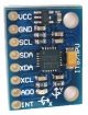
|
Motion | 3.3V - 5V | SDA/SCL or 2 digital GPIO | I²C bus | 0x68 0x69 |
no | ||
| Gases | CO2 (ppm) | 5V (not over 5.2V!) |
2 digital GPIO (Software-Serial) | serial | N/A | no | Pins (4x + 5x) C-C2.54mm |
32mm x 19.5mm x 8.2mm | |
| GPIO | LED, tones, servos etc. | 1.8V - 2.2V (max) | 1 PWM GPIO | - | N/A | no | - | - | |
| GPIO | Relay | 5V (3.3V - 5V Logic) |
1 digital GPIO, per relay | - | N/A | no | - | - | |
| GPIO | Output | 3.3V - 12V (general) | 1 digital GPIO, per servo | - | N/A | no | - | - | |
| Communication | Output | 1V - 1.5V (general) | 1 digital GPIO | - | N/A | no | - | - | |
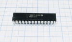
| Extra IO | PCF8574 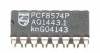
|
Input / output | 2.5V - 6V | SDA/SCL or 2 digital GPIO | I²C bus | 0x40-0x4F | no | - | - |
| Extra IO | PCA9685 
|
Output | 2.3V - 5.5V | SDA/SCL or 2 digital GPIO | I²C bus | 0x40-0x7F | no | - | - |
| Motor | Adafruit Motor Shield v2 
|
Output | 3.3V | SDA/SCL or 2 digital GPIO | I²C bus | 0x60-0x80 | no | - | - |
| Notify | Buzzer 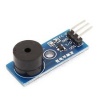
|
Output | 3V - 5V (general) | 1 digital GPIO | - | N/A | no | - | - |
| Extra IO | PWM GPIO (IRF520) 
|
Output | 3.3V or 5V | 1 digital GPIO | - | N/A | no | - | - |
| Display | Output | 5V (general) | SDA/SCL or 2 digital GPIO | I²C bus | 0x27 | no (yes if you use 5V logic and the ESP unit can't handle that voltage on GPIO) |
- | - | |
| Display | Output | 3.3V or 5V (general) | SDA/SCL or 2 digital GPIO | I²C bus | 0x3C | no (yes if you use 5V logic and the ESP unit can't handle that voltage on GPIO) |
- | - | |
| Display | Output | 5V (general) | Rx/Tx or 2 digital GPIO | Serial | N/A | No The display outputs 3.2 volts max. |
4 holes | - | |
| Generic | Level shifter (level converter) | 3.3V - 5V | Used inline with the wires. | no | N/A | This is the level shifter, aka logic converter. Used to turn logics of higher voltage (5V) down to ESP friendly voltage (3.3V). | - | - | |
| Notify | MP3 player | 3.3V - 5V | 1 digital GPIO (TX) | no | N/A | - | - | - | |
| Notify | MP3 player | 3.3V - 5V | 1 digital GPIO (TX) | no | N/A | - | - | - | |
| Keypad | Input | 2.4V - 5.5V | 2 digital GPIO | NON-STANDARD I²C bus |
N/A | - | Ø? (2x) C-C? |
- | |
| Switch input | Input | 3.3V | 2 digital GPIO 3 GPIO if "0" is used |
no | N/A | - | Ø? (2x) C-C? |
- | |
| Notify | Output | GPIO-power | 1 digital GPIO | - | N/A | no | - | - | |
| Notify | Output | GPIO-power | 1 digital GPIO | - | N/A | no | - | - | |
| Display | Output | 3.3V - 5V | 2-3 digital GPIO | - | N/A | no | - | - |

