First step:
Go to "Tools" and click "I²C Scan".
You should get back a list like this:
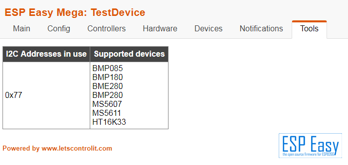
- BMP180-I2C_Scan-Results.jpg (102.97 KiB) Viewed 11082 times
.
If you get a "No I2C devices found", the sensor does not answer.
In this case, check your cabling - a common mistake is swapping SCL and SCA or power cabling failures.
Check the "Hardware" settings too if the settings for I²C pins is correct.
(Should be set to GPIO4 & GPIO5).
Otherwise if the BMP180 is detected correctly please post a screenshot of the device settings.
Please remember that I²C is not suitable for long lines, it is limited to "In box connecting".
More info in the Wiki:
https://www.letscontrolit.com/wiki/inde ... he_I²C_Bus
The sensor module runs quite well on 3,3V. The sensor itself has a voltage supply of 1,8...3,6V.
On the board avoltage regulator is placed (the black three-pinned part), so there is no matter
if you feed 3,3V or 5V als long as the power supply is reliable.
All BMP and BME sensors i use run on 3,3V without problems.
Due to the article LisaM linked the ESP can take 5V at the inputs under certain circumstances.
There are specific GPIO settings that will produce too much current over the GPIO and then
the ESP dies. As we usually don't control these settings i won't recommend to connect 5V to the GPIOs.
Anyways, as this breakout board has a voltage regulator, it will not push 5V to the GPIOs so no worries.
Regards
Shardan
 and for wiring it's basic ! I wired the 2 i2C lines according to setup of ESP, and then wired GND and Vin to 3.3V !