OK step by step.
For all ESp module if you switch it on and there is no code chaching state of the output the pinoutput is LOW!!!!!! or not active or what you want to call it.
LEDS only.
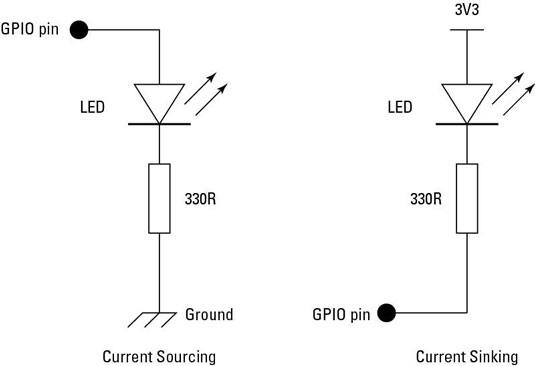
You are switching VCC by the ESP pin!!!!! not GND so you use current sourcing.
ESP is swithed OFF.
You connect led with serial resistor between ESP pin and gnd.
LED is OFF as the pin is LOW.
ESP is switched ON.
LED is OFF as output is active LOW.
Now with OPEN HAB you can send HIGH signal to ligth up LED (active HIGH) and send LOW signal to dim LED (active LOW).
SO HIGH is LED ON and LOW is LED OFF.
- opto2.jpg (14.46 KiB) Viewed 21699 times
Relay only.
You are switching GND by the ESP pin.
ESP is swithed OFF.
Your relay board first needs a VCC 3.3volt and a GND connection to work at all.
And you connect an input wire pin of relay board to an ESP pin.
Relay is OFF.
ESP is switched ON.
Relay is switched ON. Dang this is not what you want...... but the ESP pin is LOW at start up?!?!
Measure it with a simple DVM digital volt meter.
The pin of the ESP is LOW and if you look at the schematics this causes the LED of the opto couler to switch the transistor and so the relay ON.
The LED of the opto coupler is switch by ground not by VCC as is the regular LED in your other connection.
Now you toggle the state of the relay in OPENHAB and then an active HIGH from OPENHAB causes the optocoupler led to dim and switch OFF the relay. So reverse of what you want. And toggle will change state but in opposite way as with a cold start up.
An active LOW switch ON the relay. This is called reverse logic.
If you connect your regular LED to VCC and switch the GND you have the same reverse logic as with the relay board.
You are using current sinking.
All VCC points on the relay boards are connected so you cant reverse to positive switching as with the regular leds.
Let me know if this what you see happening and this answers the question.
Paco