Moderators: grovkillen, Stuntteam, TD-er
-
nietbelangrijk
- New user
- Posts: 6
- Joined: 23 Sep 2017, 14:07
#1
Post
by nietbelangrijk » 30 Jun 2019, 11:19
Got this in the mail:
SONOFF MINI IS a mini and compact DIY smart switch used for different kinds of switch boxes, even the smallest EU standard switch box. Convenient to automate your home appliances with eWeLink app through your smartphone or tablet or your voice command. Support to connect an external rocker light switch unable to automatically spring back for easily managing connected devices in your home, both on your phone or directly from the wall.
It supports the DIY mode (designed for developers) which allows users to integrate MINI into worldwide third-party open source smart home control system to achieve LAN control without cloud service, such as Home Assistant, openHAB, ioBroker .etc.
For sale at:
https://www.itead.cc/sonoff-mini.html
I wonder how to flash this with EspEasy 2.0x, anybody any experience already?
-
ThomasB
- Normal user
- Posts: 1362
- Joined: 17 Jun 2018, 20:41
- Location: USA
#2
Post
by ThomasB » 01 Jul 2019, 02:28
No experience with it, but flashing ESPEasy appears to be possible. It has a ESP8265 (1MB) and four solder pads for the serial interface. See PCB photos here:
https://fccid.io/2APN5-MINI/Internal-Ph ... os-4291787
The bad news is that the photos show that most GPIO pins don't have convenient solder pads. So plan on precise soldering to tiny naked ESP8265 pins.
And be very careful: It does not look like AC mains is electrically isolated from the low voltage DC circuitry. Until this is confirmed, treat all external connections with high voltage safety in mind.
- Thomas
-
kimot
- Normal user
- Posts: 190
- Joined: 12 Oct 2017, 20:46
#3
Post
by kimot » 02 Jul 2019, 20:46
Look for Shelly1 or Shelly2 ( Shelly2.5 ).
The same function, the same size, but TX, RX and others on connestors - no soldering.
And ESP with 4M memory on board.
http://shelly.cloud
-
vobo70
- Normal user
- Posts: 11
- Joined: 10 Oct 2016, 09:53
#5
Post
by vobo70 » 22 Sep 2019, 13:01
did anyone successfully flashed ESPEasy to sonoff mini diy?
I want just Home Assistant to control light switches at home.
So maybe to use different firmware? (eg. Tasmota)
-
Shardan
- Normal user
- Posts: 1156
- Joined: 03 Sep 2016, 23:27
- Location: Bielefeld / Germany
#6
Post
by Shardan » 22 Sep 2019, 13:15
ThomasB wrote: ↑01 Jul 2019, 02:28
No experience with it, but flashing ESPEasy appears to be possible. It has a ESP8265 (1MB) and four solder pads for the serial interface. See PCB photos here:
https://fccid.io/2APN5-MINI/Internal-Ph ... os-4291787
The bad news is that the photos show that most GPIO pins don't have convenient solder pads. So plan on precise soldering to tiny naked ESP8265 pins.
And be very careful: It does not look like AC mains is electrically isolated from the low voltage DC circuitry. Until this is confirmed, treat all external connections with high voltage safety in mind.
- Thomas
Most likely the ESP is connected to mains voltage... following the given pictures
it is a widespread capacitor-resistor- bridge rectifier circuit without transformer.
The notes on the website says:
1.The antenna has strong electricity inside, do not break the wire jacket.
so this might be another hint to no separation between ESP and mains.
This says clearly:
Use a 3,3V Power Supply for flashing!
Never ever connect the circuit to mains while connected to your PC.
Regards
Shardan
-
vobo70
- Normal user
- Posts: 11
- Joined: 10 Oct 2016, 09:53
#7
Post
by vobo70 » 23 Sep 2019, 07:44
but which firmware file use to flash sonoff mini?
ESP_Easy_mega-20190903_minimal_core_242_ESP8285_1M_OTA.bin
ESP_Easy_mega-20190903_hard_core_252_other_POW_ESP8285_1M.bin
ESP_Easy_mega-20190903_hard_other_POW_ESP8285_1M.bin
-
TD-er
- Core team member
- Posts: 9884
- Joined: 01 Sep 2017, 22:13
- Location: the Netherlands
-
Contact:
#8
Post
by TD-er » 23 Sep 2019, 11:03
I think the "minimal" build is the most practical, since it has the option for OTA updates (in 2 steps)
Just make sure you have the ESP8266/8285 right.
-
M*I*B
- Normal user
- Posts: 379
- Joined: 22 Jan 2018, 15:47
- Location: Germany
-
Contact:
#9
Post
by M*I*B » 02 Oct 2019, 14:57
... may can I steal this thread a moment?

I find this thread due searching for information if possible to flash the MINI... The Q is answered now. But in this thread I read also about the SHELLY (kimot talk about it) and I have take a look at it...
The SHELLY1 looks very nice and I believe that the SHELLY1 is a little bit smaller as the MINI... I'm right?
So what you all can say about the SHELLY1 with ESPEasy? Work that well like the SONOFF? Where are the diffences? What do you mean? SONOFF-MINI or SHELLY1? Let me know ...
(
Background: For a friend I am trying to find a solution for his extensive outdoor lighting. There are PIR motion detectors and switches. In addition, a RaspBerry with FEHM is to be used in order to be able to implement comfort functions (time, brightness, links). A classic wiring is due to the structural conditions out of the question)
DLzG
Micha
-
TD-er
- Core team member
- Posts: 9884
- Joined: 01 Sep 2017, 22:13
- Location: the Netherlands
-
Contact:
#10
Post
by TD-er » 02 Oct 2019, 22:50
The Shelly1 is supported and may be a more practical choice compared to the Sonoff's, since it has 2 MB flash.
That's a lot easier to perform OTA updates.
I believe it is smaller than the smallest Sonoff.
Just be very careful when installing the Shelly.
It has a low/high voltage jumper which must be set correct or else the magic smoke escapes.
Also there are pins for triggering the input, but those are not isolated. So they are connected to mains.
Even though the print suggests to use 10 or 16 Amp, I would advice not to run so much current through those very tiny relais (also not with the Sonoffs)
And since the unit is positioned in the wall, surrounded by concrete, you may experience worse WiFi reception.
It may help sometimes to rotate the module a bit, but that's easier said then done when connected with a number of very stiff 1.5 or 2.5 mm^2 copper cables.
-
M*I*B
- Normal user
- Posts: 379
- Joined: 22 Jan 2018, 15:47
- Location: Germany
-
Contact:
#11
Post
by M*I*B » 03 Oct 2019, 00:04
... thankz for the detailed information on the part. That sounds pretty good!
I think I'll give it a try and order a few ...
As for the WLAN: Has anyone fumbled the thing apart? Perhaps you could connect a PigTail to it with a board antenna, which you, for example, can stick directly behind the rocker switch...
DLzG
Micha
-
TD-er
- Core team member
- Posts: 9884
- Joined: 01 Sep 2017, 22:13
- Location: the Netherlands
-
Contact:
#12
Post
by TD-er » 03 Oct 2019, 10:26
The whole board is connected to mains, so if you make an external antenna to it, this will also be connected to mains.
That's quite a safety issue.
-
M*I*B
- Normal user
- Posts: 379
- Joined: 22 Jan 2018, 15:47
- Location: Germany
-
Contact:
#13
Post
by M*I*B » 03 Oct 2019, 10:39
... hmmm ... maybe ...
It is a pity that there is probably no potential separation, but this is probably due to the small footprint.
But ... If the ground potential of the electronics is internally "N", you have at the antenna a maximum of 3.3V against ground. Of course, this requires, that you have to make sure that you connect the neutral conductor to "N" of the Shelly ...
In that case, you will trigger the FI if you touch the antenna (if at all). And since the antenna is glued / clamped behind the rocker switch during operation, there is no risk of contact for the user.
... or am I just missing something?
DLzG
Micha
-
TD-er
- Core team member
- Posts: 9884
- Joined: 01 Sep 2017, 22:13
- Location: the Netherlands
-
Contact:
#14
Post
by TD-er » 03 Oct 2019, 12:39
There is no guarantee either that the "ground" on the ESP side has a direct connection to neutral.
It could very well be at some potential half way.
The only guarantee you have is that there is no galvanic isolation.
-
M*I*B
- Normal user
- Posts: 379
- Joined: 22 Jan 2018, 15:47
- Location: Germany
-
Contact:
#15
Post
by M*I*B » 03 Oct 2019, 12:44
The only guarantee you have is that there is no galvanic isolation.

that is of course true!
But the rest is ultimately just a matter of measurements, if I have such a part here.
I had read that things are open source? Then the circuit diagram would have to get somewhere, right?
DLzG
Micha
-
TD-er
- Core team member
- Posts: 9884
- Joined: 01 Sep 2017, 22:13
- Location: the Netherlands
-
Contact:
#16
Post
by TD-er » 03 Oct 2019, 13:16
"Open Source" can also indicate the firmware.
Or maybe they just want to support "Open Source" firmware versions.
They have made the flash pins easy available.
-
M*I*B
- Normal user
- Posts: 379
- Joined: 22 Jan 2018, 15:47
- Location: Germany
-
Contact:
#17
Post
by M*I*B » 03 Oct 2019, 14:20
... that can be true; I can't find a schematic right now in the web...
ABout schematic... Do you / someone use Altium Circutmaker? I'm comming from the "real" Altium-Designer but since I lost my job on DEZ'18 I'm not able to use it; much to expensive for private use. So now I will give CM a try...
DLzG
Micha
-
prairietech
- Normal user
- Posts: 37
- Joined: 20 Oct 2017, 23:47
#18
Post
by prairietech » 26 Nov 2019, 18:06
Bumping this thread...........has anyone successfully flashed espeasy to a sonoff mini?
Getting ready to try and wanted to know if there was anything special I should know?
I've done several other devices but this is the first mini.
-
taylor20
- New user
- Posts: 1
- Joined: 31 Dec 2019, 18:46
#19
Post
by taylor20 » 31 Dec 2019, 18:53
Not had any luck with mine, using the curl commands:
Discover:
dns-sd -B _ewelink._tcp
Test:
curl
http://DEVICEIP:8081/zeroconf/info -XPOST --data '{"deviceid":"DEVICEID","data":{} }'
Unlock :
curl
http://DEVICEIP:8081/zeroconf/ota_unlock -XPOST --data '{"deviceid":"DEVICEID","data":{} }'
Flash Firmware:
curl
http://DEVICEIP:8081/zeroconf/ota_flash -XPOST --data '{"deviceid":"DEVICEID","data":{"downloadUrl": "
http://MACBOOKIP/ESP_20191208.bin", "sha256sum": "d5a654253f1ca5c4d170c0ae80902fd88b2deee13cd13835e65e94753a412f8c"} }'
I suspect the firmware file I chose [ESP_Easy_mega-20191208_minimal_core_242_ESP8285_1M_OTA.bin] was too large (around 600k) compared to the Tasmota (460k) which works first time.
Next attempt I will build a cut down firmware build.
-
prairietech
- Normal user
- Posts: 37
- Joined: 20 Oct 2017, 23:47
#20
Post
by prairietech » 02 Jan 2020, 00:03
Yes that is what I found works for now. It would be nice to use mqtt and get status messages back from the mini. Looks like 3D printing a programming jig with pogo pins will be needed before flashing anything via the serial port.
-
kimot
- Normal user
- Posts: 190
- Joined: 12 Oct 2017, 20:46
#21
Post
by kimot » 04 Jan 2020, 00:09
Lots of info about Sonoff Mini:
https://www.youtube.com/watch?v=fzEDFmB0UYU
Flashing firmware through wifi in time about 12:30 in this video.
Set DIY jumper to MINI.
Reconfigure your router or create hotspot on your phone with specific SSID and password according the video ( 6:21 )
Use DIYTool for finding your MINI and change SSID and wifi to your network.
Reboot MINI and it will be in your network now visible.
Flash firmware.
Use DIY Tool sw for it again.
Instead of Tasmota bin file use appropriate ESPeasy bin file.
Comparsion SHELLY and MINI:
https://www.youtube.com/watch?v=_X2Jf0093jI
Better video about flashing :
https://www.youtube.com/watch?v=9fkYBWvwn4A
-
amiable
- New user
- Posts: 7
- Joined: 20 Jan 2020, 15:20
#22
Post
by amiable » 23 Jan 2020, 22:39
kimot wrote: ↑04 Jan 2020, 00:09
Instead of Tasmota bin file use appropriate ESPeasy bin file.
ok, but which one?
ESP_Easy_mega-20191208_minimal_core_242_ESP8285_1M_OTA.bin is too big:
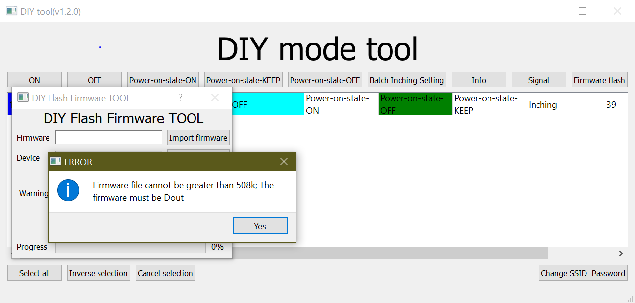
- Przechwytywanie.PNG (55.03 KiB) Viewed 64428 times
-
Grumpf
- Normal user
- Posts: 124
- Joined: 05 May 2017, 23:45
- Location: Namur
#23
Post
by Grumpf » 24 Jan 2020, 15:31
Same problem I managed to install Tasmota but then no firmware from espeasy works. Even if it's actually smaller than 508 like ESPEasy_2step_UploaderMega_1024.

-
amiable
- New user
- Posts: 7
- Joined: 20 Jan 2020, 15:20
#24
Post
by amiable » 25 Jan 2020, 21:52
I finally gave up with the OTA update. I soldered the cables and uploaded the firmware using an external programmer (ESP_Easy_mega-20191208_normal_ESP8285_1M).
-
prairietech
- Normal user
- Posts: 37
- Joined: 20 Oct 2017, 23:47
#25
Post
by prairietech » 26 Jan 2020, 01:11
Did you solder wires directly to the circuit boards pads?
-
prairietech
- Normal user
- Posts: 37
- Joined: 20 Oct 2017, 23:47
#27
Post
by prairietech » 26 Jan 2020, 13:21
Steady hands! I have seen 3D printer plans for a drop in programming fixture that uses pogo pins to make contact with the circuit board pads.
Also good to know the easy mega normal 1 meg works in the Mini.
Currently I'm just pushing http commands but it would sure be nice to use mqtt and get status responses back in mqtt.
Maybe you could start a side business programming easy mega into Minis?
-
amiable
- New user
- Posts: 7
- Joined: 20 Jan 2020, 15:20
#28
Post
by amiable » 26 Jan 2020, 16:25
prairietech wrote: ↑26 Jan 2020, 13:21
I have seen 3D printer plans for a drop in programming fixture that uses pogo pins to make contact with the circuit board pads.
Here is one of those holders (link under the movie):
https://www.youtube.com/watch?v=xEmYDLdiCnQ
prairietech wrote: ↑26 Jan 2020, 13:21
Maybe you could start a side business programming easy mega into Minis?

In that case I would invest in holder mentioned above (my colleague has a 3d printer)

-
prairietech
- Normal user
- Posts: 37
- Joined: 20 Oct 2017, 23:47
#29
Post
by prairietech » 28 Jan 2020, 14:18
Silly question......I assume the easy mega 1M version supports full mqtt including status reports from the Mini of it's on/off status and RSSI?
-
leonvolt
- New user
- Posts: 1
- Joined: 02 Feb 2020, 12:02
#30
Post
by leonvolt » 02 Feb 2020, 12:14
I've backed up the original firmware and flashed a custom firmware on a sonoff mini with my FTDI adapter without soldering, it was a little but tricky but I've used a clip to clamp a jumper wire on the 3,3 v pin and used the ground pin on top of the board, I then pressed the button that's connected to GPIO 0 and connected my FTDI adapter. I then used my hands to hold down the RX and TX pins in the flashing process. It's a bit tricky, but it works. I'm using esphome for a my sonoff device's because it gives me more freedom in how I use them. Here's a picture with my esp home configuration for the mini.
-
Attachments
-
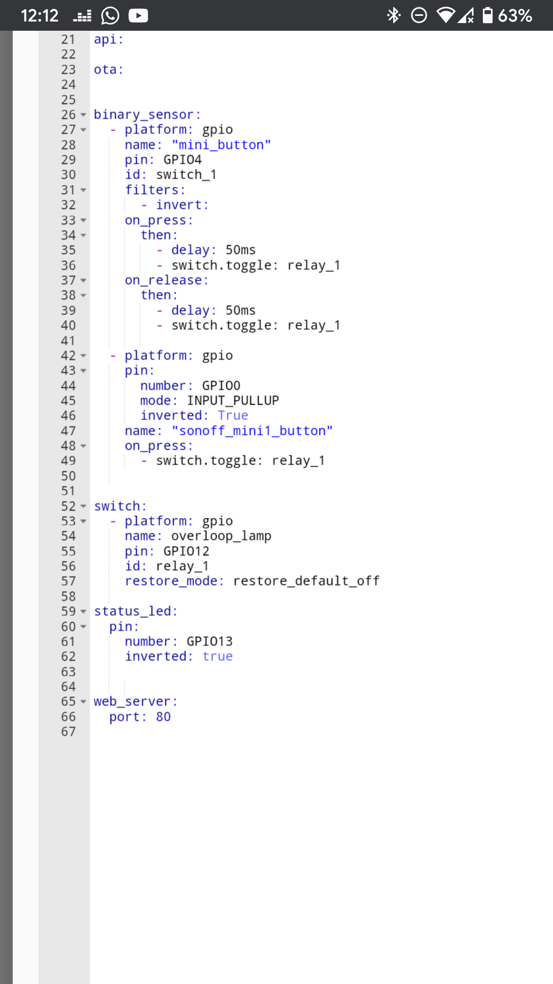
- Screenshot_20200202-121223.png (264.83 KiB) Viewed 63477 times
-
pa3gmi
- New user
- Posts: 7
- Joined: 04 Jun 2018, 15:46
#31
Post
by pa3gmi » 04 Feb 2020, 12:32
amiable wrote: ↑25 Jan 2020, 21:52
I finally gave up with the OTA update. I soldered the cables and uploaded the firmware using an external programmer (ESP_Easy_mega-20191208_normal_ESP8285_1M).
Hi,
now I have used the ESP Easy Flasher with the ESP_Easy_mega-20191208_normal_ESP8285_1M file in combination with the module seen here (
https://www.thingiverse.com/thing:3767667) mini is now listening to my commands from Domoticz
For people who will have some Pogo pins, I have some here for postage in the Netherlands.
-
Mintgroen
- New user
- Posts: 1
- Joined: 24 Sep 2020, 22:38
#32
Post
by Mintgroen » 24 Sep 2020, 22:53
I just flashed a Mini with Tasmota-lite as a test, following this guide:
https://sigmdel.ca/michel/ha/sonoff/sonoff_mini_en.html
I used the curl method on my rpi4 running Apache as the fileserver. Some fiddling with the strings did the trick because the strings in de guide use line breaks /, that didn't work for me, putting the complete string in one go worked. Next job is to get espeasy on the minis.
Who is online
Users browsing this forum: No registered users and 20 guests


