I have been having the same issue with the false positives given by the HC-SR501 PIR sensor board.
I have searched and tried almost everything I could find about fixing this issue but nothing helped.
I know that my post is long but I like to describe the reasoning behind the changes and not just give people a short solution. if you look for that stop here and just try to solder a wire across the 18K resistor that is on top of the sensitivity potentiometer. Also make sure you let us know if it worked for you.
Then I start learning how it works and found this AN4368 Application note from ST (
http://www.st.com/resource/en/applicati ... 096551.pdf) This helped me understand how any PIR circuit should work.
The two BISS0001 datasheets I found useful are:
https://www.mpja.com/download/31227sc.pdf and
https://cdn-learn.adafruit.com/assets/a ... SS0001.pdf
Maybe somebody that knows more can correct me if I am wrong here but my understanding is as follow:
When moving in front of the sensor because of the two windows the signal should go low then high or high then low these two peaks should count as a single movement.
There is not much info about the BISS001 IC but found that I could tap at both the Vout1 and Vout2 aka the two stages of the analog side of the circuit.
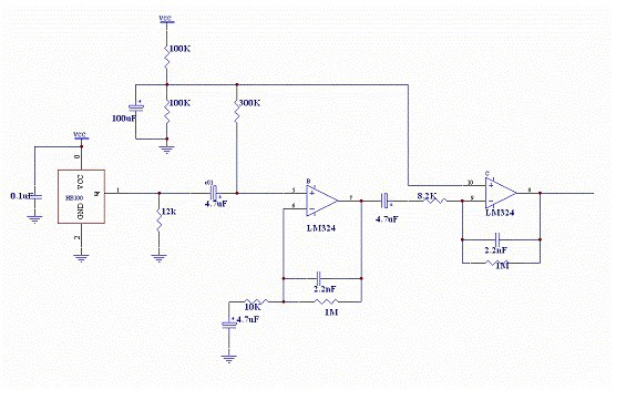
So I got the signal from the stage2 out pin 12 and created my own simple circuit using two comparators so I can see the output signal.(this is just trying to mimic their circuit inside the IC)
What this BISS001 IC is doing based on the schematics is that uses the two comparators and an OR logic to transform the small negative and positive peaks into digital peaks and enable the output when detecting such peaks. Now even if they would count every two peaks as one still there is no way to differentiate between the one negative and one positive or two positive peaks thus noise on the positive side could introduce more positive peaks and trigger the output with no negative peaks present.
The datasheet shows the VH=0.7VDD and VL=0.3VDD So using 10x 4K7 resistors in series between 3.3V and ground I have created my own reference ladder for the comparators and used 2 LEDs to see the output signal (actually hookup an old oscilloscope too on the input to my comparator to see the raw signal too).
This is what I found: It seems that the VH is not really 0.7VDD but more toward 0.6VDD thus triggering much easier. (positive noise could make it trigger much easier).
With this circuit I found that there is a lot of noise on the positive side of the comparator (that LED blinks much more even when not moving and seems to be correlated as many people pointed out with the ESP8266 WiFi activity).
If the BISS001 would have more logic inside to look for both peaks negative and positive and account them as a single peak then this IC would have been immune to the noise on the positive side.
From experimenting for few hours with it found that the negative peak had much less noise so I start comparing the different schematics I could find on the internet and using the App Note mentioned above calculated Gain and filter frequencies for the first stage. After redrawing the diagram I found that there is a 18K resistor between the PIR sensor and the input1 (hmm some schematics use it others are not).
So I thought why attenuating the signal before the amplifier ?And I said to myself if I can raise the signal level up I could make the system think that there are no positive peaks and I could trick the BISS0001 to only count the negative peaks and did solder a wire across the 18K resistor. The signal level raised slightly and became less noisy (now I would love to have a better DSO oscilloscope to actually capture the signal, with my analog scope I could only see the signal live) system started to behave better and the LED on the high side even at 0.6VDD will not trigger anymore even when moving in front of the sensor while the low side would still trigger when moving my hand in front.
It would be good if somebody with more experience and better equipment can reproduce this experiment and get better measurements or simply explain to me that I am doing something wrong.
PS: In the end I am not really sure if the BISS001 has an OR GATE or an AND GATE to combine the comparators signals. From my experiments seems that is an AND GATE.