Hello everyone,
I’m working on a project with an ESP32 and ESP-Easy to manage my pool’s filtration system. Currently, the time is synchronized via the Internet, but I’d like to set up a solution to maintain the time even if the Internet connection is lost, using a DS3231 module with a backup battery.
Context:
• My ESP32 gets the time via NTP (Network Time Protocol) when the Internet connection is available.
• However, my pool equipment is located quite far from my house, and sometimes the Internet connection drops. In that case, I’d like the time to be maintained locally with a module like the DS3231, so everything keeps working properly even without the Internet.
• Once the Internet connection is restored, the time should be updated again via the NTP server and synchronized with the DS3231.
• Every day at 9:00 AM, the ESP32 analyzes the water temperature and decides whether the pool pump should be turned on or off. If the temperature is high enough, the pump is turned on, controlled by a relay.
• The relay’s state needs to be saved to prevent data loss in case of power or Internet outages.
• Since the pump’s operation is only evaluated once per day, there will be only one relay state saved per day. I plan to use a dummy device in ESP-Easy to store this state easily without cluttering the memory.
Questions:
1. Retrieving the Time with the DS3231:
• Is it possible with ESP-Easy to retrieve the time from the DS3231 module when the Internet is unavailable?
• The DS3231 should continue to provide accurate time using its backup battery during Internet outages.
• When the Internet connection is restored, is it possible to update the time from the NTP server and synchronize it back to the DS3231 module?
2. Using the EEPROM in the DS3231:
• The DS3231 has an integrated EEPROM. Is it possible to use this memory to save the state of my pool pump relay (just one relay) so that it can be restored after a power outage?
• Can the relay state be stored in the EEPROM without affecting the RTC’s timekeeping accuracy?
3. Other Compatible Modules with ESP-Easy:
• Are there other RTC modules with internal memory, such as the PCF8583 or RTC1307, that are compatible with ESP-Easy and could help save both the time and relay states in case of power or Internet outages?
• Can these modules be used to achieve a similar setup to the DS3231, where the time is synced via NTP when the Internet is available and maintained locally when it is not?
4. Using the Internal Memory of the ESP32 (Flash/PROM):
• If no external module is compatible or simple enough to use, would it be possible to save the relay state directly to the ESP32’s internal memory (Flash or PROM)?
• Since the relay state is only saved once per day (at 9:00 AM), would this frequent writing affect the ESP32’s lifespan due to the limited number of write cycles for flash memory?
• Considering it’s just one save per day, would the impact on memory be negligible, or should I consider another solution for long-term reliability?
Recommended Modules:
• DS3231: An RTC module with a backup battery to maintain time during power outages. It also has EEPROM memory that could potentially be used to save the relay state. This module seems to be a good option for both time management and data storage when the Internet is unavailable.
• PCF8583, RTC1307: Other RTC modules with internal memory that could potentially be used for storing time and relay states.
Thanks in advance for your help and suggestions!
Using the DS3231 Module and Other Modules for Time and Relay State Management with ESP-Easy
Moderators: grovkillen, Stuntteam, TD-er
Re: Using the DS3231 Module and Other Modules for Time and Relay State Management with ESP-Easy
1)
There is a number of RTC clocks supported.
You can see them on the tools->Advanced page under "Time Source" -> "External Time Source"
The DS3231 is among them.
This will then work exactly as you think it will.
So whenever ESPEasy updates its local time, it will update the RTC clock and when booting and the RTC clock is detected and has a plausible time (later timestamp than compile time), the local time will be synced from the RTC clock.
When syncing time among ESPEasy p2p nodes, there is some mechanism to determine which node has the most accurate time.
The time source + last sync time is then taken into account (e.g. GPS > NTP > p2p > RTC )
However there is a bug report that if some node is using deep sleep, it may have the shortest "time since sync" which may trigger all nodes in the network to adopt that time. So better not use deep sleep in this setup for now until that's fixed.
2)
The EEPROM is not yet supported.
About the rest of your remark about a pump state...
I strongly suggest to design your setup in such a way that if you get a power outage, you make sure to have the pump in a known state.
Apart from that, it still is better to actually check the pump state instead of relying on a stored or remembered state as this will at some point get out of sync with reality.
3)
Here is a list of all supported RTC clock modules: https://espeasy.readthedocs.io/en/lates ... ime-source
These all work the same.
4)
There is 1 plugin which can store a state. This is the "level" plugin: https://espeasy.readthedocs.io/en/lates ... #p021-page
Saving a state once a day is probably fine.
Usually I would suggest to go for a build using LittleFS, but since saving the settings on LittleFS does do quite a lot of writing, maybe for this specific setup you could go for a SPIFFS build (the builds without "LittleFS" in the name)
LittleFS does not allow a small update somewhere in the file.
It needs to rewrite everything after that change. (maybe the entire file, not 100% sure)
SPIFFS does allow mid-file changes much more easily at the cost of file system fragmentation. So maybe it makes sense to reboot ESPEasy every week or so as the GarbageCollection is called right before mounting the file system.
At some point in the future, there will be EEPROM support to store such flags, but that isn't there yet.

Re: Using the DS3231 Module and Other Modules for Time and Relay State Management with ESP-Easy
If knowing the state of the pool pump after power failure recovery is critical, then you could use a DPDT latching relay. These have two coils, set and reset.
One set of contacts on it could be connected to a GPIO input pin for reading its state after a power outage. The other set of contacts could be used to power your pool pump power contactor.
Another advantage is that current consumption is less. Because the relay only needs power for a moment. This would allow longer battery life if you want to add that sort of thing to this project.
- Thomas
Re: Using the DS3231 Module and Other Modules for Time and Relay State Management with ESP-Easy
Hello everyone,
First of all, thank you for your quick and detailed responses.
Time Synchronization with DS3231
Since ESP-Easy updates the ESP32’s time in the order GPS > NTP > p2p > RTC, this works perfectly with the DS3231. My question is: once the DS3231 device is created and configured, will everything work automatically as described, or is any additional configuration required?
PCB Design – Choosing a DS3231 Module
I am currently designing my PCB and realized I forgot to include the DS3231. I am now debating between two DS3231 modules:
Module 1:

Very small and square – ideal for a compact PCB.
Uses a non-replaceable, rechargeable button battery.
However, it exhibits significant time drift.
Module 2:

Larger in size.
Has a replaceable battery and an integrated EEPROM.
It is rated much better in terms of time drift, making it the best option currently.
If the ESP32 automatically updates to the correct time via NTP after a power outage, does that mean the smaller module (even with its higher drift) would be acceptable since it will be corrected upon synchronization? I would appreciate your opinions on this.
Other Points
Deep Sleep:
I’m not entirely sure what deep sleep is, but if it’s some kind of standby mode, I don’t believe my ESP32 uses it. Therefore, it shouldn’t be an issue for my setup.
EEPROM Implementation:
Implementing EEPROM support appears too complex for my current level, so I plan to avoid that solution.
Pump State Feedback via Optocoupler:
I already use an optocoupler (230V/5V) to obtain feedback on the pump’s state after a power outage, which lets me know the actual state of the pump. However, my main requirement is that the pool filtration relay resumes its initial state automatically after a power outage.
Managing the Pool Filtration Relay State:
Here is the current setup:
Every day at 9:00 AM, the ESP32 checks the water temperature and, based on that, runs the pool pump for a duration determined by the temperature (for example, if the water is 24°C, the pump runs from 9:00 AM to 4:00 PM).
Upon boot, an ESP-Easy safety feature turns off all relays, and a second safety rule turns off the filtration relay every day at 10:00 PM.
As a result, in the event of a power outage, the filtration remains off, which is problematic.
To solve this, I am considering creating a rule that activates the filtration daily (with a duration that varies based on the temperature) within a specific time window (e.g., between 9:00 AM and 4:00 PM). This way, even if there’s a power outage, if the ESP32 boots and the current time is within that window, the filtration will automatically resume. Currently, I’m using a rule with various timers based on the temperature. I’d like to know if this approach is feasible.
Thank you again for your help and suggestions. I look forward to your feedback to finalize my design.
Best regards,
Attached is my PCB currently in progress:
First of all, thank you for your quick and detailed responses.
Time Synchronization with DS3231
Since ESP-Easy updates the ESP32’s time in the order GPS > NTP > p2p > RTC, this works perfectly with the DS3231. My question is: once the DS3231 device is created and configured, will everything work automatically as described, or is any additional configuration required?
PCB Design – Choosing a DS3231 Module
I am currently designing my PCB and realized I forgot to include the DS3231. I am now debating between two DS3231 modules:
Module 1:
Very small and square – ideal for a compact PCB.
Uses a non-replaceable, rechargeable button battery.
However, it exhibits significant time drift.
Module 2:
Larger in size.
Has a replaceable battery and an integrated EEPROM.
It is rated much better in terms of time drift, making it the best option currently.
If the ESP32 automatically updates to the correct time via NTP after a power outage, does that mean the smaller module (even with its higher drift) would be acceptable since it will be corrected upon synchronization? I would appreciate your opinions on this.
Other Points
Deep Sleep:
I’m not entirely sure what deep sleep is, but if it’s some kind of standby mode, I don’t believe my ESP32 uses it. Therefore, it shouldn’t be an issue for my setup.
EEPROM Implementation:
Implementing EEPROM support appears too complex for my current level, so I plan to avoid that solution.
Pump State Feedback via Optocoupler:
I already use an optocoupler (230V/5V) to obtain feedback on the pump’s state after a power outage, which lets me know the actual state of the pump. However, my main requirement is that the pool filtration relay resumes its initial state automatically after a power outage.
Managing the Pool Filtration Relay State:
Here is the current setup:
Every day at 9:00 AM, the ESP32 checks the water temperature and, based on that, runs the pool pump for a duration determined by the temperature (for example, if the water is 24°C, the pump runs from 9:00 AM to 4:00 PM).
Upon boot, an ESP-Easy safety feature turns off all relays, and a second safety rule turns off the filtration relay every day at 10:00 PM.
As a result, in the event of a power outage, the filtration remains off, which is problematic.
To solve this, I am considering creating a rule that activates the filtration daily (with a duration that varies based on the temperature) within a specific time window (e.g., between 9:00 AM and 4:00 PM). This way, even if there’s a power outage, if the ESP32 boots and the current time is within that window, the filtration will automatically resume. Currently, I’m using a rule with various timers based on the temperature. I’d like to know if this approach is feasible.
Thank you again for your help and suggestions. I look forward to your feedback to finalize my design.
Best regards,
Attached is my PCB currently in progress:
- Attachments
-
- Capture d’écran 2025-02-02 à 12.20.22.png (360.84 KiB) Viewed 13244 times
-
- Capture d’écran 2025-02-02 à 12.01.23.png (226.28 KiB) Viewed 13246 times

Re: Using the DS3231 Module and Other Modules for Time and Relay State Management with ESP-Easy
A solution for this is on the TODO list
/Ton (PayPal.me)
Re: Using the DS3231 Module and Other Modules for Time and Relay State Management with ESP-Easy
First of all, let's start with the PCB design and safety...
I think your 'low voltage' part of the design is too close to mains voltage pins.
There is still some solder mask present, which also does isolate traces, but since you're using through-hole components, you have to take extra care especially in humid environments.
So for now, I would suggest to mount that PCB vertical in such a way that the mains voltage parts cannot drip any condensation water on low voltage parts (or vice verse).
For example with the USB connector pointing up.
Maybe also place some plastic strip between the 230V and "Temp-1" screw terminal. I usually make a slid in the PCB between such terminals carrying higher voltages.
I don't see the 5k1 resistors on both CC pins of the USB-C connector. Or is this a micro-USB connector? (there are USB-C connectors with limited set of pins, that's why I ask...)
I notice you're using both an ADC and 1-wire sensors.
Some of those Ali-Express sold 1-wire sensors do have a metal enclosure which is electrically connected to GND (probably a manufacturer mistake as there is no need for it)
However if you have an electrical connection between the metal enclosure and some other applicance which is connected through GND, you can have strange offsets in your DC-measurement and the metal enclosure of the temperature sensor will corrode quite fast.
Also make sure to check the logs of ESPEasy regarding the ADS1115. It is very likely the seller is sending you an ADS1015 or some clone.
The difference is sample rate and resolution.
Clone chips sometimes report the ADC value of another pin or just ignore settings like resolution.
About the RTC clock module.
One with a rechargable battery is nice to have, however keep in mind these can only be used in a limited temperature range.
Also not sure if there is a charge-monitor on that cheap board. Most of those do not like being charged over 3V.
How much is this 'significant time drift' ? Seconds per day?
Keep in mind there is no battery voltage monitoring on those modules as far as I know. This means you will only find out when you need the RTC clock.
You can also consider using a GPS module when the unit does have a clear view of the sky.
Re: Using the DS3231 Module and Other Modules for Time and Relay State Management with ESP-Easy
Hi everyone,
Thank you very much for your detailed responses. I apologize for my delayed reply; I'm not an electronics engineer and have been working on designing this PCB for about a month, so the process has been quite challenging.
1. Regarding PCB Design and Safety:
You mentioned:
"First of all, let's start with the PCB design and safety... I think your 'low voltage' part of the design is too close to mains voltage pins. There is still some solder mask present, which also does isolate traces, but since you're using through-hole components, you have to take extra care especially in humid environments. So for now, I would suggest to mount that PCB vertical in such a way that the mains voltage parts cannot drip any condensation water on low voltage parts (or vice verse). For example with the USB connector pointing up. Maybe also place some plastic strip between the 230V and 'Temp-1' screw terminal. I usually make a slit in the PCB between such terminals carrying higher voltages."
I will increase the spacing in the routing and the ground plane between the high voltage and low voltage sections. Furthermore, my PCB will be housed in a box that is mounted vertically against a wall and located in a closed room.
My question: For my ground plane design, should I implement it only on the component side, or should I use both sides of the PCB, connected by vias? Your advice on the best approach would be greatly appreciated.
2. Regarding the USB Port:
You stated:
"I don't see the 5k1 resistors on both CC pins of the USB-C connector. Or is this a micro-USB connector? (there are USB-C connectors with limited set of pins, that's why I ask...)"
I am using a USB Type-C 3A 6-pin port solely to power the enclosure at 5V from an external supply (like those used for mobile phones). I have designed the PCB to allow a choice between a 230V supply and a 5V USB Type-C supply (here is the manufacturer's link: [datasheet link]). I am not entirely sure if the 5k1 resistors are necessary in this configuration, so I appreciate your input on that.
3. Regarding the ADS1115:
You mentioned:
"Also make sure to check the logs of ESPEasy regarding the ADS1115. It is very likely the seller is sending you an ADS1015 or some clone. The difference is sample rate and resolution. Clone chips sometimes report the ADC value of another pin or just ignore settings like resolution."
I will ensure to purchase an original ADS1115. Although I haven't used it yet, I have included it in the design as a precaution for a future upgrade—specifically for measuring the pH of my pool water.
4. Regarding the RTC Module:
You stated:
"About the RTC clock module. One with a rechargeable battery is nice to have, however keep in mind these can only be used in a limited temperature range. Also not sure if there is a charge-monitor on that cheap board. Most of those do not like being charged over 3V. How much is this 'significant time drift'? Seconds per day? ... Keep in mind there is no battery voltage monitoring on those modules as far as I know. This means you will only find out when you need the RTC clock. You can also consider using a GPS module when the unit does have a clear view of the sky."
I am still undecided on which RTC module to choose. Its role would be to maintain the correct time in case of an Internet outage, and potentially for future enhancements. Could you please suggest a model or advise which one would be best for my application?
Thank you again for your valuable and detailed feedback.
Best regards,
Re: Using the DS3231 Module and Other Modules for Time and Relay State Management with ESP-Easy
If you have the option, please mount it with the high-voltage side at the bottom.Neoseb38 wrote: ↑08 Feb 2025, 10:22 1. Regarding PCB Design and Safety:
[...]
I will increase the spacing in the routing and the ground plane between the high voltage and low voltage sections. Furthermore, my PCB will be housed in a box that is mounted vertically against a wall and located in a closed room.
My question: For my ground plane design, should I implement it only on the component side, or should I use both sides of the PCB, connected by vias? Your advice on the best approach would be greatly appreciated.
Preferrably in such a way that if condensation water drips down, it never forms a 'path' from low-voltage to high voltage.
I always use 'copper pour' in my PCB designs and connect it to GND.
Of course not on high-voltage areas.
So you design your board layout and then draw a copper pour area on both sides of your PCB on the low-voltage areas.
Whenever you let the board re-route, you can generate this copper pour area again or it will be recreated automatically.
This copper pour has several functions:
- Limit noise
- Improve ground in your circuit
- Offer a level surface for components to be mounted.
This last funtion is less important for through-hole components, but may make quite a difference when using SMT assembly.
The parts will be much more mechanically stable. For example large capacitors could otherwise 'wobble' a bit and then the solder joints may break.
I don't see no datasheet link.Neoseb38 wrote: ↑08 Feb 2025, 10:22 2. Regarding the USB Port:
You stated:
"I don't see the 5k1 resistors on both CC pins of the USB-C connector. Or is this a micro-USB connector? (there are USB-C connectors with limited set of pins, that's why I ask...)"
I am using a USB Type-C 3A 6-pin port solely to power the enclosure at 5V from an external supply (like those used for mobile phones). I have designed the PCB to allow a choice between a 230V supply and a 5V USB Type-C supply (here is the manufacturer's link: [datasheet link]). I am not entirely sure if the 5k1 resistors are necessary in this configuration, so I appreciate your input on that.
If the USB-C connector does not offer CC1/CC2 pins, then you don't need to add those 5k1 resistors.
If those are present, you should add those between CC1 and GND and CC2 and GND.
If you don't then there is no guarantee the USB power supply you plan on using will deliver the required amount of current, or even stays on.
Maybe best to wire it up to test.Neoseb38 wrote: ↑08 Feb 2025, 10:22 3. Regarding the ADS1115:
You mentioned:
"Also make sure to check the logs of ESPEasy regarding the ADS1115. It is very likely the seller is sending you an ADS1015 or some clone. The difference is sample rate and resolution. Clone chips sometimes report the ADC value of another pin or just ignore settings like resolution."
I will ensure to purchase an original ADS1115. Although I haven't used it yet, I have included it in the design as a precaution for a future upgrade—specifically for measuring the pH of my pool water.
As I said, there are quite a lot of sellers selling a fake module.
Simple way to test is to make a small array of resistors (e.g. 100k or 10k, doesn't really matter as long as they are in the same order of resistance)
Then connect them like this:
3V3 --- R --- A0 --- R --- A1 --- R --- A2 --- R --- A3 --- GND
This way each analog input has a different but constant voltage to measure.
Then enable the 'stats' option in ESPEasy and let it run for a while.
There only should be some noise, but not much.
For fake modules, the measured voltage may be from the wrong pin, thus the voltage will either hop around a lot or all pins report the same voltage.
Then the swap between ADS1015 and ADS1115.
One has lower resolution but higher possible sample rate.
ESPEasy should be able to detect this and tell you in the logs what it found.
If not, try to see what the smallest 'jump' in sampled values is with the resistor-array and you can see if it was 12 bit or 9 bit.
Well you have to chose between the following:Neoseb38 wrote: ↑08 Feb 2025, 10:22 4. Regarding the RTC Module:
[...]
I am still undecided on which RTC module to choose. Its role would be to maintain the correct time in case of an Internet outage, and potentially for future enhancements. Could you please suggest a model or advise which one would be best for my application?
- Using a coin sell; You have no idea when the battery is discharged other than that the system doesn't know the time when you actually need it.
- Using a rechargable battery; These should have some charging circuit or else it might damage the cell. No idea how long those keep their charge, but typically those RTC clock chips have extremely low current requirements... when their board is well designed.
I doubt any clock drift is a problem in this setup. Even if the clock is off by a few minutes, then it really isn't that big of a deal, right?
In the ESPEasy rules, you can also check whether the time has been set (%isntp%) and if the battery of a RTC module is empty, the RTC clock will likely show a very unlikely year like 1970.
So you could check the %sysyear% to be > 2024 and less than 2038
Re: Using the DS3231 Module and Other Modules for Time and Relay State Management with ESP-Easy
Thank you again for your clear and precise response.
Here is the link to my USB Type-C connector:
https://www.lcsc.com/product-detail/USB ... 68623.html
Datasheet
I found it on the LCSC website to have it directly mounted on my PCB via EasyEDA.
Unfortunately it does have CC1 and CC2 pins.
Do USB Type-C connectors exist that don’t require additional resistors?
So far, in my test circuit, everything is powered through this USB connector, and I don’t see any resistors:
https://fr.aliexpress.com/item/10050058 ... pt=glo2fra
Regarding the RTC module, indeed, time drift wouldn’t be a big issue for my project as long as the time resynchronizes with the internet after a potential power outage.
This one interests me the most due to its small size:
https://techmaze.romman.store/product/99187741
It’s really tiny, and I think that by adding a small male Dupont connector on my PCB, it could work just fine.
However, I doubt that the battery is rechargeable.
Tough choice!
Here is the link to my USB Type-C connector:
https://www.lcsc.com/product-detail/USB ... 68623.html
Datasheet
I found it on the LCSC website to have it directly mounted on my PCB via EasyEDA.
Unfortunately
Do USB Type-C connectors exist that don’t require additional resistors?
So far, in my test circuit, everything is powered through this USB connector, and I don’t see any resistors:
https://fr.aliexpress.com/item/10050058 ... pt=glo2fra
Regarding the RTC module, indeed, time drift wouldn’t be a big issue for my project as long as the time resynchronizes with the internet after a potential power outage.
This one interests me the most due to its small size:
https://techmaze.romman.store/product/99187741
It’s really tiny, and I think that by adding a small male Dupont connector on my PCB, it could work just fine.
However, I doubt that the battery is rechargeable.
Tough choice!
Re: Using the DS3231 Module and Other Modules for Time and Relay State Management with ESP-Easy
TD-er wrote: ↑08 Feb 2025, 13:37 If the USB-C connector does not offer CC1/CC2 pins, then you don't need to add those 5k1 resistors.
If those are present, you should add those between CC1 and GND and CC2 and GND.
If you don't then there is no guarantee the USB power supply you plan on using will deliver the required amount of current, or even stays on.
Not having these resistors installed correctly was the cause for many USB-C power supplies and power-banks not supplying 5V on the first revision of Raspberry Pi 4 boards (except for the original RPi USB-C power supply). They fixed that in later revisions.Neoseb38 wrote: ↑08 Feb 2025, 14:51 Do USB Type-C connectors exist that don’t require additional resistors?
So far, in my test circuit, everything is powered through this USB connector, and I don’t see any resistors:
https://fr.aliexpress.com/item/10050058 ... pt=glo2fra
So, having those 5k1 resistors in place can be important. Better safe than sorry
/Ton (PayPal.me)
Re: Using the DS3231 Module and Other Modules for Time and Relay State Management with ESP-Easy
Like this?
- Attachments
-
- Capture d’écran 2025-02-08 à 15.13.03.png (370.41 KiB) Viewed 12879 times
Re: Using the DS3231 Module and Other Modules for Time and Relay State Management with ESP-Easy
Yep, from the CC1/2 pins, 1 resistor per pin to GND.
N.B. these CC-pins did not exist on USB-A connectors, so if you have an USB power supply only using USB-A connectors (the old rectangular ones), it will probably work just fine without those resistors, though it is depending on the USB cable used.
Since your connector does not have the data pins available, those might be pulled down by the USB host and thus it might conclude no device is plugged in and then starts 'polling' for a device and thus constantly turning off/on the 5V.
That's why it also matters which cables you use. And no I don't know which cable/power supply will work anyway regardless whether you connect a non-standard USB device.
I can only say that since I started using those IKEA USB cables, I have had no more issues like these.
Re: Using the DS3231 Module and Other Modules for Time and Relay State Management with ESP-Easy
I'm not sure I understood correctly.TD-er wrote: ↑08 Feb 2025, 16:38 Yep, from the CC1/2 pins, 1 resistor per pin to GND.
N.B. these CC-pins did not exist on USB-A connectors, so if you have an USB power supply only using USB-A connectors (the old rectangular ones), it will probably work just fine without those resistors, though it is depending on the USB cable used.
If I leave the resistors and, let's say, power this connector using a smartphone USB-A charger with a USB-A to USB-C cable, would it still work?
Re: Using the DS3231 Module and Other Modules for Time and Relay State Management with ESP-Easy
Yes, as the USB-A power supply won't(read: can't) probe the CC pins to determine if it should switch the power on. It will just supply the power
/Ton (PayPal.me)
Re: Using the DS3231 Module and Other Modules for Time and Relay State Management with ESP-Easy
Sadly it is more complex and there isn't a definite "yes" or "no".
There are several possibilities here:
- USB charger/powerbank/power supply may stop supplying 5V every now and then when it doesn't 'see' a device connected
- USB-A to -C cables may or may not actively 'pull' the data lines up.
You have to know that the USB standard defines a device to be 'disconnected' when both data lines are pulled low.
So some USB-A to -C cables may have some internal resistors to pull the data lines to somewhere in the middle of their supposed range and some of them rely on the resistors connected between the CC-pins and GND.
This way, the USB charger may still consider the device connected and will allow to output at least 500 mA.
I don't know whether your USB-C header does also 'fake' some "connected state" on both data pins or not, as it doesn't allow for any actual USB device to be present.
So as you can see, there are a lot of "maybe" and assumptions.
Anyway, it is better to have those 5k1 resistors present as that's how it is supposed to be.
And if you encounter USB chargers to drop the 5V every now and then, you know you need to try again with either a different charger or different cable (or both).
Re: Using the DS3231 Module and Other Modules for Time and Relay State Management with ESP-Easy
Hi everyone,
First of all, thank you for your help and advice, especially regarding the resistors for the USB-C port!
I’ve also added a female Dupont connector to my PCB with VCC, GND, SDA, and SCL to support a DS3231 RTC module ([this version](https://passionelectronique.fr/tutorial-ds3231/), which includes an EEPROM and a temperature sensor).
This way, I can keep this option for later use.
Since the module has two connectors, I decided to use the one without the male pins, which seemed more practical.
Now, about my PCB project for managing two swimming pools:
 My pool: Uses a contactor for filtration.
- I currently use an Arduino with a 5V 10A relay module, but I had issues with random restarts.
- The solution was adding a snubber module to the contactor, and everything has been working perfectly for years.
 My father-in-law’s pool: A Desjoyaux pool that does not use a contactor.
- The pump is 450W / 2.1A.
- I currently control it with an Arduino and a 5V 10A relay module, and it works fine.
- However, I’m concerned that over time, the relay contacts may wear out.
I'm looking for a more robust and versatile solution that can handle both setups:
 A 30A relay module ([see here](https://m.media-amazon.com/images/I/61A ... L1500_.jpg))
A 40A SSR relay (but will it overheat due to the pool pump's power consumption?)
Adding a diode to protect against inductive loads?
Keeping the snubber for the pool that uses a contactor?
Do you have any recommendations?
Thanks again for your help and valuable advice!
First of all, thank you for your help and advice, especially regarding the resistors for the USB-C port!

I’ve also added a female Dupont connector to my PCB with VCC, GND, SDA, and SCL to support a DS3231 RTC module ([this version](https://passionelectronique.fr/tutorial-ds3231/), which includes an EEPROM and a temperature sensor).
This way, I can keep this option for later use.
Since the module has two connectors, I decided to use the one without the male pins, which seemed more practical.
Now, about my PCB project for managing two swimming pools:
 My pool: Uses a contactor for filtration.
 - I currently use an Arduino with a 5V 10A relay module, but I had issues with random restarts.
- The solution was adding a snubber module to the contactor, and everything has been working perfectly for years.
 My father-in-law’s pool: A Desjoyaux pool that does not use a contactor.
 - The pump is 450W / 2.1A.
- I currently control it with an Arduino and a 5V 10A relay module, and it works fine.
- However, I’m concerned that over time, the relay contacts may wear out.
I'm looking for a more robust and versatile solution that can handle both setups:
 A 30A relay module ([see here](https://m.media-amazon.com/images/I/61A ... L1500_.jpg))
  A 40A SSR relay (but will it overheat due to the pool pump's power consumption?) Adding a diode to protect against inductive loads? Keeping the snubber for the pool that uses a contactor?
 Do you have any recommendations?
Thanks again for your help and valuable advice!
Re: Using the DS3231 Module and Other Modules for Time and Relay State Management with ESP-Easy
Most SSR's can only switch AC loads as they only switch during a 0-crossing.
No idea what kind of filtering is needed to switch a pump.
I think a snubber circuit does make sense, but no idea about the specifics of an inductive load as a pump.
A diode doesn't make sense on an AC load.
You could add TVS diodes which trigger at 400 (??) volt.
But maybe someone else has better ideas about this.
When using SSR, make sure there is enough cooling and keep in mind whether the cooling pad is connected to mains or not.
Re: Using the DS3231 Module and Other Modules for Time and Relay State Management with ESP-Easy
I just received the 5V 30A relay module as a replacement for the smaller 10A relay module, and it works perfectly (both unloaded and with a simple 230V 60W light bulb).
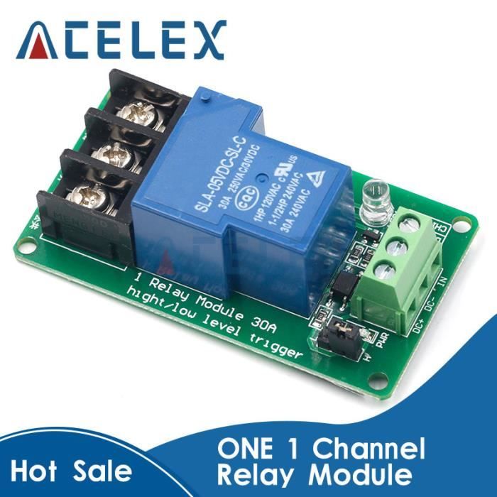
I doubt this module can handle such high currents, but since high-power filtration pumps use a contactor and only low-power pumps don’t, I’d say that for a 500W pump, considering the startup peak, the current shouldn’t exceed 16A, and only for a very short time.
Of course, I will add an RC snubber in parallel with the contactor.

I tested the GND and GPIO2 pins that activate the relay, and I’m getting 3.15V, while the relay is powered at 5V.
So, it looks ESP32-compatible, meaning I can skip the logic level converter and save space on my PCB.
I also tested the status feedback using my 230V to 5V optocoupler, which connects through the PCF8574 module.
Since this module is powered via I2C at 3.3V, and despite the 5V coming from the optocoupler, the I2C voltage remains stable.

As integrating this module into my PCB was too complicated, I just hope I didn’t make a mistake by directly implementing the PCF8574 chip on my PCB.
For the PCB routing, I used:
2mm traces for AC
0.5mm traces for DC
What do you think?
I doubt this module can handle such high currents, but since high-power filtration pumps use a contactor and only low-power pumps don’t, I’d say that for a 500W pump, considering the startup peak, the current shouldn’t exceed 16A, and only for a very short time.
Of course, I will add an RC snubber in parallel with the contactor.
I tested the GND and GPIO2 pins that activate the relay, and I’m getting 3.15V, while the relay is powered at 5V.
So, it looks ESP32-compatible, meaning I can skip the logic level converter and save space on my PCB.
I also tested the status feedback using my 230V to 5V optocoupler, which connects through the PCF8574 module.
Since this module is powered via I2C at 3.3V, and despite the 5V coming from the optocoupler, the I2C voltage remains stable.
As integrating this module into my PCB was too complicated, I just hope I didn’t make a mistake by directly implementing the PCF8574 chip on my PCB.
For the PCB routing, I used:
2mm traces for AC 0.5mm traces for DCWhat do you think?
Re: Using the DS3231 Module and Other Modules for Time and Relay State Management with ESP-Easy
The trace-width should be related to the max. current.
The used voltage doesn't have anything to do with the trace width. The distance between traces is what matters with higher voltages.
As a rule of thumb, keep at least 1 mm per 100 V.
For mains voltage this means you need to keep at least 3 mm between traces and preferrably double it for solder joints. (the 'green' solder mask on your PCB is a remarkable good isolator)
For power nets upto 1A, I typically use 15 - 20 mil trace width. When you really need to carry a beefy current, don't hesitate to use wider traces and multiple vias when you need to switch layers for such a current.
About switching the relays...
You better still use a FET or normal transistor to switch the relais as the GPIO pin of an ESP can only source a few 10s of mA.
Also don't forget to add a diode over the coil to protect the electronics when you switch the coil current to 0 as the coil will then generate very high voltages (can be as high as > 1000V) to keep the magnetic field the same.
If such a circuit is already present on your relay module, then you don't need to add it of course.
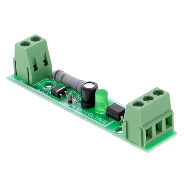
Those "230V to optocoupler" boards like the one you're showing is quite a waste of energy.
See the beefy resistor, which has to be this large for a reason.
If it is just an occasional detection, then it is probably not an issue, but keep in mind this is quite wasteful when ran continously.
Please do test whether the PCF module is what you need.
It is a rather old design and I know there were some users having issues with these.
Not sure what those issues were, but I think you may be able to find it on this forum somewhere.
The used voltage doesn't have anything to do with the trace width. The distance between traces is what matters with higher voltages.
As a rule of thumb, keep at least 1 mm per 100 V.
For mains voltage this means you need to keep at least 3 mm between traces and preferrably double it for solder joints. (the 'green' solder mask on your PCB is a remarkable good isolator)
For power nets upto 1A, I typically use 15 - 20 mil trace width. When you really need to carry a beefy current, don't hesitate to use wider traces and multiple vias when you need to switch layers for such a current.
About switching the relays...
You better still use a FET or normal transistor to switch the relais as the GPIO pin of an ESP can only source a few 10s of mA.
Also don't forget to add a diode over the coil to protect the electronics when you switch the coil current to 0 as the coil will then generate very high voltages (can be as high as > 1000V) to keep the magnetic field the same.
If such a circuit is already present on your relay module, then you don't need to add it of course.
Those "230V to optocoupler" boards like the one you're showing is quite a waste of energy.
See the beefy resistor, which has to be this large for a reason.
If it is just an occasional detection, then it is probably not an issue, but keep in mind this is quite wasteful when ran continously.
Please do test whether the PCF module is what you need.
It is a rather old design and I know there were some users having issues with these.
Not sure what those issues were, but I think you may be able to find it on this forum somewhere.
Re: Using the DS3231 Module and Other Modules for Time and Relay State Management with ESP-Easy
Thank you for your clarification.TD-er wrote: ↑10 Feb 2025, 21:53 The trace-width should be related to the max. current.
The used voltage doesn't have anything to do with the trace width. The distance between traces is what matters with higher voltages.
As a rule of thumb, keep at least 1 mm per 100 V.
For mains voltage this means you need to keep at least 3 mm between traces and preferrably double it for solder joints. (the 'green' solder mask on your PCB is a remarkable good isolator)
For power nets upto 1A, I typically use 15 - 20 mil trace width. When you really need to carry a beefy current, don't hesitate to use wider traces and multiple vias when you need to switch layers for such a current.
So, if I set the AC part with a 2mm trace width and 3mm spacing between traces, and 0.5mm for all DC traces with a 0.3mm spacing, it should be okay?
Am I really required to add this? If so, what exact component should I use, and how should I connect it to my PCB?About switching the relays...
You better still use a FET or normal transistor to switch the relais as the GPIO pin of an ESP can only source a few 10s of mA.
Also don't forget to add a diode over the coil to protect the electronics when you switch the coil current to 0 as the coil will then generate very high voltages (can be as high as > 1000V) to keep the magnetic field the same.
If such a circuit is already present on your relay module, then you don't need to add it of course.
(Sorry, but I don’t know much about this, and I’ve been struggling with this PCB for a month now, all alone, with no prior knowledge
 )
)I can't tell if this is already installed on the relay module since I don’t know what it looks like.
Can I remove my logic level converter since my GPIO is correctly running at 3.3V?
Currently, without adding anything except powering the relay module (both the 10A and 30A versions) with 5V, everything works perfectly—but only with a lightbulb connected. I have RC snubbers in case I need them for the pump or the contactor.
It’s the same with my old Arduino-based system, which has been running for three years now. Just the Arduino and a relay module, plus a snubber on the pump contactor. (Although the relays are smaller, rated at 10A.)

The optocouplers are working well on my old Arduino system too.Those "230V to optocoupler" boards like the one you're showing is quite a waste of energy.
See the beefy resistor, which has to be this large for a reason.
If it is just an occasional detection, then it is probably not an issue, but keep in mind this is quite wasteful when ran continously.
They allow me to check if the filtration is actually running or if it has been activated by another means besides the relay (such as the pool’s antifreeze system, a manual switch, or the original timer in the pool’s electrical panel).
They also help me monitor the status of my pool heat pump, which I connected to a small relay (dry contact wired to the on/off button of the remote control). This is very useful for knowing its actual state.
Regarding the PCF, I looked at both of your links, but to be honest, I didn’t understand much of your discussion. You really need to be an expert in electronics for that!Please do test whether the PCF module is what you need.
It is a rather old design and I know there were some users having issues with these.
Not sure what those issues were, but I think you may be able to find it on this forum somewhere.
The only thing I can say is that currently, on my prototype, I am using a PCF8574 module, and it works perfectly. So far, I haven’t had any issues in my tests.
Due to the limited number of available GPIOs on my ESP32 ETH01, I am using the PCF8574 exclusively for my switches connected to GND:
Forced filtration mode
Stop mode
Auto/manual mode switch
"Auto" mode for ESP Easy rules
"Manual" mode for using the pool’s original system
I also use it to monitor the state of the 230V optocouplers.
I just hope that on my PCB, I have correctly integrated the PCF8574 chip, the pull-up resistors, and properly connected the A0, A1, and A2 pins to GND to maintain the same default address as the module.
The relays and temperature sensors are connected directly to the ESP32.
Re: Using the DS3231 Module and Other Modules for Time and Relay State Management with ESP-Easy
Well if the PCF... is working fine in your setup, then there is nothing to worry.
It is just that there are some situations where one of the other supported GPIO-expanders are more suitable.
In your PCB drawing tool you probably have some option for "copper pour".
This way you can draw an area and assing a net to it (e.g. GND).
What this does is it will fill up any holes between the traces with copper and connect it to this copper pour net.
This way you have much wider traces at no extra costs.
Since you have 2 sides of your PCB, you could use GND on the bottom and 3V3 at the top.
When you place the parts not too tightly packed on the PCB, there is lots of room between the traces and thus you'll have a proper power net on your boards without much to worry about.
N.B. do not use copper pour near high voltage nets.
The relay board you have seem to have some extra parts, so it looks like these actually do have an optocoupler on the module.
Thus the load of that relay board to your ESP is the same as if you're connecting a LED.
This way you probably don't need to add any level converters for them to use.
The reason I mentioned those 230V optocoupler boards is not that they're not useful.
Only that they are quite wasteful regarding energy consumption.
If you only have them effectively connected to a motor or a pump when it is turned on, then it probably is just fine.
I just advice against running them 24/7 to detect power outages for example as that's quite a waste of energy.
Those large resistors are a hint about how much power they will consume. Looks like at least 1 Watt, probably more.
Back in the days a kWh only costs 21 cent, it was an easy conversion; 1 Watt continuously over a year costs 2 euro.
Now that the kWh prices are closer to 40 cent per kWh, it is already 4 euro per year in electricity costs when such a module is connected to mains power 24/7.
Re: Using the DS3231 Module and Other Modules for Time and Relay State Management with ESP-Easy
Super, one less problem... or at least I hope so!Well if the PCF... is working fine in your setup, then there is nothing to worry.
It is just that there are some situations where one of the other supported GPIO-expanders are more suitable.

I'm designing my PCB with EasyEDA. I have an icon named Copper Area.In your PCB drawing tool you probably have some option for "copper pour".
This way you can draw an area and assing a net to it (e.g. GND).
What this does is it will fill up any holes between the traces with copper and connect it to this copper pour net.
This way you have much wider traces at no extra costs.
Since you have 2 sides of your PCB, you could use GND on the bottom and 3V3 at the top.
When you place the parts not too tightly packed on the PCB, there is lots of room between the traces and thus you'll have a proper power net on your boards without much to worry about.
N.B. do not use copper pour near high voltage nets.
I had already used it to create a ground plane on both sides, connected with vias, but I'll follow your advice and do as you suggested:
The copper side for GND
The component side for 3.3V
My PCB is already quite packed, as it's 8x8 cm and has around 15 vias on two layers.
Of course, I’m keeping a large clearance for the 230V traces.
Indeed, I forgot to mention it, but the module does include an optocoupler (YYG-3 high-power bidirectional isolation relay 30A (5VDC) from Amazon).The relay board you have seem to have some extra parts, so it looks like these actually do have an optocoupler on the module.
Thus the load of that relay board to your ESP is the same as if you're connecting a LED.
This way you probably don't need to add any level converters for them to use.
Another good news!

Now I better understand what you meant.The reason I mentioned those 230V optocoupler boards is not that they're not useful.
Only that they are quite wasteful regarding energy consumption.
If you only have them effectively connected to a motor or a pump when it is turned on, then it probably is just fine.
I just advice against running them 24/7 to detect power outages for example as that's quite a waste of energy.
Those large resistors are a hint about how much power they will consume. Looks like at least 1 Watt, probably more.
Back in the days a kWh only costs 21 cent, it was an easy conversion; 1 Watt continuously over a year costs 2 euro.
Now that the kWh prices are closer to 40 cent per kWh, it is already 4 euro per year in electricity costs when such a module is connected to mains power 24/7.
In fact, my optocoupler will only notify me when the pump is running, but more importantly when it's activated outside of the relay.
My wife tends to turn on the pump using the original switch from time to time, and she sometimes forgets to turn it off!

Anyway, thank you a thousand times for your help!
I can finally move forward with my pool project, and I’m crossing my fingers that the PCB will work once completed.
The power protection components, resistors, and the PCF8574 chip are my biggest concerns, but I think it should be fine!
Just need to remove the logic level converter, and it should be good to go!
- Attachments
-
- Capture d’écran 2025-02-11 à 18.11.29.png (370.23 KiB) Viewed 11272 times
Re: Using the DS3231 Module and Other Modules for Time and Relay State Management with ESP-Easy
One more thing...
You seem to have 5V to your PH sensor.
What (analog) voltage does this sensor return?
The analog input of the ADS1x15 should not exceed the supply voltage. (3V3)
And the 1-wire sensors...
They both use the same GPIO pin, so you technically only need a single pull-up resistor.
How long will the wires be from the board to those sensors?
With 2 sensors it probably isn't that much of an issue, but typically you should not have an Y-shaped bus.
Now you have a very short trace from the ESP to the bus and then the sensors 'pointing away' so it is more like a normal bus.
But still if running long wires, this might be an issue.
The on/off switch and the modes switch do not have a pull-up resistor from 3V3 to their non-GND pins.
Maybe good idea to at least add those pads on the PCB to place some 10k resistor (or 4k7, doesn't really matter what exact value you're using) when it might be needed.
No idea how strong the pull-up resistors in the PCF are, but they might not be enough if those switches have long wires to them and pick up all kinds of noise.
Re: Using the DS3231 Module and Other Modules for Time and Relay State Management with ESP-Easy
Indeed, I recently replaced the 3.3V with 5V because one of the PH modules I found required 5V. I thought that, just like the PCF which was powered by 3.3V and received 5V from the optocouplers without affecting the I2C voltage, it would be the same.You seem to have 5V to your PH sensor.
What (analog) voltage does this sensor return?
The analog input of the ADS1x15 should not exceed the supply voltage. (3V3)
So, I’ll switch it back to 3.3V; there are plenty of PH modules that work from 3V to 5V, so it will be fine. Anyway, many say that PH readings are fine but problematic over time because they require regular adjustments/calibration. I’ve made it optional
But thanks for the info, I’m correcting it right away.
Regarding the 2 temperature probes, I have to say that, indeed, the distance of one probe (the water temperature one) is very long… at least 8 metersAnd the 1-wire sensors...
They both use the same GPIO pin, so you technically only need a single pull-up resistor.
How long will the wires be from the board to those sensors?
With 2 sensors it probably isn't that much of an issue, but typically you should not have an Y-shaped bus.
Now you have a very short trace from the ESP to the bus and then the sensors 'pointing away' so it is more like a normal bus.
But still if running long wires, this might be an issue.
Currently, I’ve never had a problem with the Arduino version that is working right now. On the Arduino, I soldered resistors directly onto each of the wires of the DS18B20 probes, and the 2 probes are connected to the same GPIO. I was planning to do the same.
I didn’t quite understand the Y story.
Do you advise me to remove one terminal block and connect both probes directly to a single terminal block?
For the switches, initially, I had them connected directly to a GPIO of the ESP32. But that caused problems and wasn’t reliable at all. They would turn on or off by themselves, I can’t remember exactly.The on/off switch and the modes switch do not have a pull-up resistor from 3V3 to their non-GND pins.
Maybe good idea to at least add those pads on the PCB to place some 10k resistor (or 4k7, doesn't really matter what exact value you're using) when it might be needed.
No idea how strong the pull-up resistors in the PCF are, but they might not be enough if those switches have long wires to them and pick up all kinds of noise.
It was only when I connected them to the PCF module that everything worked perfectly without any issues. I had actually bought this module for that purpose, if I remember correctly, because I had read somewhere that it was great for switches, relays, and anything binary.
Re: Using the DS3231 Module and Other Modules for Time and Relay State Management with ESP-Easy
Typically a 'bus' is a straight line with sensors connectors at a short distance from the 'bus'
And about the switches with long cables.
The cables will act as an antenna.
If you add a pull-up resistor to the GPIO, it needs more energy to toggle the logic state.
Code: Select all
Short distance from the bus:
_____________________________________
        |         |         |        |
        T         T         T        T


Y-shaped bus:
                    ___________________Y
                    |
____________________|
                    |
                    |
                    ___________________T
And about the switches with long cables.
The cables will act as an antenna.
If you add a pull-up resistor to the GPIO, it needs more energy to toggle the logic state.
Re: Using the DS3231 Module and Other Modules for Time and Relay State Management with ESP-Easy
Thanks again for all your help.
I think I've finally finished (after a month, lol).
I know it's not perfect, and the placement of the AC components is not optimal compared to the DC ones.
However, I tried my best to follow your recommendations, and this PCB will be installed in an IP65 enclosure, mounted vertically in a closed room.
I routed the entire PCB with a 0.5mm trace width and 0.3mm spacing for the DC part, and a 2mm trace width with 3mm spacing for the high-voltage section.
I added some safety measures for the 230V/5V power supply (HLK-10M05), as well as the recommended 5.1kΩ resistors on CC1 and CC2 of the USB Type-C port.
I also placed a 4.7kΩ pull-up resistor for the two DS18B20 temperature sensors and rearranged the connectors to minimize Y-split connections as much as possible.
I replaced the 5V power supply with 3.3V for the ADS1115.
I added available vias for 5V, GND, and 3.3V under the ESP32 ETH01, just in case, as well as four vias to potentially add pull-up resistors for my switches, as you had suggested (also under the ESP32).
I also removed the logic level shifter, added vias for a Dupont connector to optionally connect a DS3231 module under the ADS1115 (this way, I can solder a Dupont connector onto the module's solderable area).
As you also suggested, I added a 3.3V copper pour on the component side (red on the layout) and a GND copper pour on the bottom side.
I will solder the JST connectors myself to avoid any mismatch with the female connectors.
- Attachments
-
- Capture d’écran 2025-02-13 à 16.25.14.png (225.15 KiB) Viewed 10571 times
-
- Capture d’écran 2025-02-13 à 16.24.53.png (157.76 KiB) Viewed 10571 times
-
- Capture d’écran 2025-02-13 à 16.24.42.png (214.2 KiB) Viewed 10571 times
-
- Capture d’écran 2025-02-13 à 16.24.28.png (369.55 KiB) Viewed 10571 times
-
- Capture d’écran 2025-02-13 à 16.23.58.png (360.05 KiB) Viewed 10571 times
Re: Using the DS3231 Module and Other Modules for Time and Relay State Management with ESP-Easy
What is the distance between the traces near the solder joint of the fuse?
And why not place C1 near the DC output of the HLK net transformer?
Another thing I forgot to mention (didn't think of it myself...)
You now have quite a lot of parts and copper near the WiFi antenna.
Usually you want to have the antenna on the edge of the board, but since you also wanted to have the USB connector on the edge you're quite limited to where to place the ESP board.
What you can do is use longer pin headers to lift the ESP board a bit further away from the PCB.
It is best not to stack those headers as that will eventually lead to bad connections. (you may try though for testing if distance makes a difference)
You could exclude the area near the antenna from your copper pour area (on both sides of the PCB)
I did find one big error when looking at your schematic...
You have directly connected the USB-C connector to the output of the HLK...
Please check if the HLK accepts 5V on its output when it is turned off in the datasheet of that module.
For sure you should never (!!) connect it to an external power supply or a PC while the unit is also powered via the HLK.
It is best to add some diodes (1A capable, like 1N4007 or something similar) between the HLK and your 5V net and the USB and 5V net.
One more possible optimization (you can do it also on later designs, just to keep in mind) is that you now have GND traces routed on the top layer.
Of course, there will always be some parts of these traces which have to be routed on 'the other side', but when possible you could 'flip' those to the side where you have the GND copper pour and then the autorouter will find it easier to route your board.
For example the trace from GND of the ADS1115 to the capacitor and then to the "Temp-2" header doesn't need to be there on the top layer as it is likely already routed on the bottom layer
And why not place C1 near the DC output of the HLK net transformer?
Another thing I forgot to mention (didn't think of it myself...)
You now have quite a lot of parts and copper near the WiFi antenna.
Usually you want to have the antenna on the edge of the board, but since you also wanted to have the USB connector on the edge you're quite limited to where to place the ESP board.
What you can do is use longer pin headers to lift the ESP board a bit further away from the PCB.
It is best not to stack those headers as that will eventually lead to bad connections. (you may try though for testing if distance makes a difference)
You could exclude the area near the antenna from your copper pour area (on both sides of the PCB)
I did find one big error when looking at your schematic...
You have directly connected the USB-C connector to the output of the HLK...
Please check if the HLK accepts 5V on its output when it is turned off in the datasheet of that module.
For sure you should never (!!) connect it to an external power supply or a PC while the unit is also powered via the HLK.
It is best to add some diodes (1A capable, like 1N4007 or something similar) between the HLK and your 5V net and the USB and 5V net.
Code: Select all
HLK --->|--- 5V
USB --->|--- 5V

"--->|---" is diode
One more possible optimization (you can do it also on later designs, just to keep in mind) is that you now have GND traces routed on the top layer.
Of course, there will always be some parts of these traces which have to be routed on 'the other side', but when possible you could 'flip' those to the side where you have the GND copper pour and then the autorouter will find it easier to route your board.
For example the trace from GND of the ADS1115 to the capacitor and then to the "Temp-2" header doesn't need to be there on the top layer as it is likely already routed on the bottom layer
Re: Using the DS3231 Module and Other Modules for Time and Relay State Management with ESP-Easy
Oof, thank you very much! I hadn't noticed the distance between the fuse terminal and the track going up to the negative terminal of C1.
I'm going to place C1 at the top, near the 5V of the power supply.
As for the antenna, indeed, I had thought about it and already read about it. I'll exclude copper areas around the antenna.
Regarding the power supply, I suspected that both shouldn't be connected at the same time. However, if I can add a safety measure, I agree.
If I add the two diodes, assuming that the HLK advises against powering the 5V when the 230V is cut off, would that solve this issue?
As for the diodes, should I place them like this?
There's quite a list of 1N4007, would this one be fine? (1A 1V@1A 1kV SOD-123FL General Purpose Diodes ROHS)
As for the traces routed on the top layer (shown in blue), it might be because the view is displaying both layers. You can even see the silkscreen on the copper side (under the ESP32).
Thanks again!
- Attachments
-
- Capture d’écran 2025-02-13 à 17.59.46.png (155.32 KiB) Viewed 10554 times
Re: Using the DS3231 Module and Other Modules for Time and Relay State Management with ESP-Easy
I would place the capacitor C1 inbetween the 2 diodes, so the + of the capacitor is at the +5V net symbol.
This way the C1 will also help when you power it via USB.
The orientation of the 2 diode is correct.
This way there is no current flowing in the wrong direction.
I just named the 1N4007 as that's one of the most standard diodes out there capable of handling 1A.
You can also pick 1N4001, or 1N4002 ... 1N4007.
The last digit is about the max. voltage, however the 1N4001 is also good enough with its 35V max. voltage. (1N4007 is upto 700V)
There are lots of other options, maybe even better ones, as the 1N400x does have quite a significant voltage drop of about 0.8V.
If you never ever will connect the USB while also connected via mains power, then you could leave out the diode for the USB port.
This way you won't run into problems with the "5V" input voltage on the ESP board if your USB cable isn't thick enough.
The 0.8V drop from the HLK is probably not a problem as there is no extra voltage drop from USB cable/USB connector.
One more thing...
Do you have the 220 uF capacitor at hand? If so, please check if it will fit inside the enclosure where you plan on placing it.
It does look a bit 'small' for 220 uF.
Re: Using the DS3231 Module and Other Modules for Time and Relay State Management with ESP-Easy
Thanks again for the info! I want to avoid any issues as much as possible, so if I can prevent problems with USB cable thickness, etc., I'll remove the USB diode and keep the current diode on the HLK side.
As for the capacitor, I don't have it on hand; I was planning to have it soldered during the PCB fabrication.
It's this model:
https://www.lcsc.com/product-detail/Alu ... 43319.html
However, I just realized I forgot something important!
An ON/OFF switch for the enclosure!
But how should I place it, considering there are two power supply options?
Should I place two vias on the PCB, where I can solder two wires to cut the 5V? For example, after the diode?
- Attachments
-
- Capture d’écran 2025-02-13 à 18.40.34.png (170.12 KiB) Viewed 10538 times
Re: Using the DS3231 Module and Other Modules for Time and Relay State Management with ESP-Easy
Would losing so much voltage due to the diode cause power issues for the ESP and the relay modules, optocouplers, etc.? And what if I replaced it with a 3-position switch? This way, I would have the option to choose between the 230V power supply, USB, or even off in the middle position.
Re: Using the DS3231 Module and Other Modules for Time and Relay State Management with ESP-Easy
3-position switch is also a good idea.
And since you're switching only 5V, you don't need to keep that much distance.
Just make sure you're not placing the switch close to the mains voltage parts
And maybe use one that's not that accessible so you can't switch it by accident.
If you plan on letting them solder the capacitor, you'd better not use a through-hole part for it as that will cost you more.
Re: Using the DS3231 Module and Other Modules for Time and Relay State Management with ESP-Easy
This time, I hope it's the right one.
So, I replaced the diodes with a 3-pin male connector to avoid the voltage drop caused by the diode on the 5V line.
With this connector, I can choose between USB or mains power using a jumper, and maybe later, a switch.
I also moved the capacitor as you advised and reworked the PCB.
+3.3V copper pour on the component side.
GND copper pour on the bottom side.
I just hope I didn't make any mistakes in the routing.
Edit: Edit: I just corrected the small copper trace leading to the fuse.
- Attachments
-
- Capture d’écran 2025-02-15 à 14.49.42.png (232.12 KiB) Viewed 10045 times
-
- Capture d’écran 2025-02-15 à 14.48.46.png (219.57 KiB) Viewed 10045 times
-
- Capture d’écran 2025-02-15 à 14.48.31.png (294.42 KiB) Viewed 10045 times
-
- Capture d’écran 2025-02-15 à 14.48.18.png (379.48 KiB) Viewed 10045 times
-
- Capture d’écran 2025-02-15 à 14.47.54.png (227.06 KiB) Viewed 10045 times
-
- Capture d’écran 2025-02-15 à 14.46.25.png (268.07 KiB) Viewed 10045 times
-
- Capture d’écran 2025-02-15 à 14.45.48.png (363.99 KiB) Viewed 10045 times
Re: Using the DS3231 Module and Other Modules for Time and Relay State Management with ESP-Easy
Hmm the position of the switch is a bit tricky.
Most of those switches have a metal enclosure and you need to reach it with your hands.
Does your fuse have a plastic cap or is the fuse reachable by hand?
You always need to assume you're not the only one to operate the unit.
If the fuse isn't shielded with a plastic enclosure, you should add something there to provide shielding.
Do you have a 3D printer?
Or maybe you can cut some shield from a "Chinese take-out box".
To quote Dave from EEVBlog: "My Chinese take-out oopsie box" when he covers his mains connected parts with one of those food boxes from the local Chinese restaurant so he can't touch those parts by accident... or when things go wrong his parts don't fly away too far
I think you made huge progress in your design
Re: Using the DS3231 Module and Other Modules for Time and Relay State Management with ESP-Easy
By the way, do you have those connectors for Temp1/2 ?
Please try to put them together and measure the distance between the pins.
I assume those are the green kinds which you can plug in a screw terminal connector?
Those have notches so you can fit them together in a row.
However you now have not joined them, but I wonder if this will push them apart too far so they won't fit in the solder holes.
Also please try to fit the intended cables in the screw terminal.
I've also had to make a new board design once to go from 2.54mm pitch to 3.81 mm pitch, or even 5.08 mm pitch as the intended cables won't fit.
Re: Using the DS3231 Module and Other Modules for Time and Relay State Management with ESP-Easy
It's a fuse holder with plastic protection.
https://www.lcsc.com/product-detail/Fus ... 68205.html
For the 3-pin connector, I mainly plan to use a jumper—worst case, I have tweezers, lol.
As for the connectors, yes, they are exactly what you're thinking of, and I already have some on hand. But to avoid issues, I'm going to have them pre-soldered at the factory on the PCB.
https://www.lcsc.com/product-detail/Scr ... 74882.html
I also made sure not to join them together, just in case I had to solder them myself and they didn’t fit properly.
Only the JST connectors won't be soldered by JLCPCB, just in case my female connectors don't match.
For the temperature sensors, no worries, they fit well.
However, I will indeed try using 1.5mm² solid core wire for the 230V power supply.
PS: Yes, I just got a brand new 3D printer (Bambu Lab A1)!

Re: Using the DS3231 Module and Other Modules for Time and Relay State Management with ESP-Easy
I must admit that placing the jumper won't be easy given the limited space. But hey, it's only supposed to be set once, so it should be manageable.
And honestly, I don't feel like redoing everything. I should have placed it vertically.
And honestly, I don't feel like redoing everything.
I should have placed it vertically.Re: Using the DS3231 Module and Other Modules for Time and Relay State Management with ESP-Easy
Do you think I can place an order?
Have you ever ordered from JLCPCB?

In red, what would be factory soldered.
Have you ever ordered from JLCPCB?
In red, what would be factory soldered.
Re: Using the DS3231 Module and Other Modules for Time and Relay State Management with ESP-Easy
I don't see the image.
And yes, I have placed quite a lot of orders at JLCPCB.
And yes, I have placed quite a lot of orders at JLCPCB.
Re: Using the DS3231 Module and Other Modules for Time and Relay State Management with ESP-Easy
Sorry.
92 euros for 5 PCBs with Euro Packet shipping.
What do you think?
92 euros for 5 PCBs with Euro Packet shipping.
What do you think?
- Attachments
-
- d363a6a928aa42c38aa3312e8ece85a9_T.png (1.13 MiB) Viewed 8191 times
Re: Using the DS3231 Module and Other Modules for Time and Relay State Management with ESP-Easy
I think it is a bit more expensive then expected.
Probably because they charge extra per 'difficult component'.
Through-hole components are always tricky for them as they need to be placed manual.
Is this with the VAT handling by them included?
If not, then you need to take extra VAT handling into account.
I always let them handle the VAT declaration, which is slightly more expensive, but at least it doesn't take weeks for customs to handle your package. (well doesn't always take weeks, but it can take upto 30 days if you're out of luck)
Typically the Dutch postal services charge 15 - 17,50 euro for handling the VAT declaration.
Re: Using the DS3231 Module and Other Modules for Time and Relay State Management with ESP-Easy
Oh and when you place a fuse, I think 1A is a bit too much.
At least make sure to take a 'slow' one. 500 mA should be enough, but the power-on surge can be quite a lot, that's why you need a "slow" one.
At least make sure to take a 'slow' one. 500 mA should be enough, but the power-on surge can be quite a lot, that's why you need a "slow" one.
Re: Using the DS3231 Module and Other Modules for Time and Relay State Management with ESP-Easy
I haven't placed my order yet, but I'll have to replace some components that are no longer in stock... I don't really feel like redoing everything on my designs, so I'll see if I can modify it directly on the site during the order process. I haven't fully figured out how it works yet.
For the shipping fees, I did some research online and made the right choice by selecting EuroPacket.
Here’s what I found on this topic:
To avoid additional customs fees when ordering from JLCPCB to France, it's recommended to choose a shipping option that includes VAT and customs fees in the delivery cost. Here are the best options:
EuroPacket → This is often the safest option to avoid customs fees. Taxes are usually included in the shipping price.
DHL Duty Paid (DHL DDP - Delivered Duty Paid) → If available, this option means that JLCPCB pays the customs fees in advance.
Other express carriers (DHL, FedEx, UPS, etc.) → These options may result in customs fees and VAT to be paid upon delivery.
And I'm still hesitating on the PCB color Blue or white
For the shipping fees, I did some research online and made the right choice by selecting EuroPacket.
Here’s what I found on this topic:
To avoid additional customs fees when ordering from JLCPCB to France, it's recommended to choose a shipping option that includes VAT and customs fees in the delivery cost. Here are the best options:
EuroPacket → This is often the safest option to avoid customs fees. Taxes are usually included in the shipping price.
DHL Duty Paid (DHL DDP - Delivered Duty Paid) → If available, this option means that JLCPCB pays the customs fees in advance.
Other express carriers (DHL, FedEx, UPS, etc.) → These options may result in customs fees and VAT to be paid upon delivery.
And I'm still hesitating on the PCB color
 Blue or white
Re: Using the DS3231 Module and Other Modules for Time and Relay State Management with ESP-Easy
Don't pick white PCB, as any flaw like soldering too long will be visible where the white solder mask is discolored.
I usually pick the DHL option, but what's best may differ per country.
You can search for replacement parts and edit them in the BOM file.
Some may not have a footprint, which will result in a rotated preview.
I usually pick the DHL option, but what's best may differ per country.
You can search for replacement parts and edit them in the BOM file.
Some may not have a footprint, which will result in a rotated preview.
Re: Using the DS3231 Module and Other Modules for Time and Relay State Management with ESP-Easy
Thanks again for the info.
I went back into EasyEDA, modified the BOM file, and replaced the out-of-stock components with available ones.
It automatically updated the new components in the schematic, and after updating the PCB, it also updated them in the PCB layout.
Thanks! I thought I would have to redo all my routing, etc.
As for the fuse, indeed, the HLK datasheet specifies a Slow Fuse but at 1A.
https://www.lcsc.com/datasheet/lcsc_dat ... 403745.pdf
Re: Using the DS3231 Module and Other Modules for Time and Relay State Management with ESP-Easy
Well both will burn in nearly the same time when you short circuit them.
And the traces are wide enough to handle a few Amp, so the fuse will burn first anyway.
And the traces are wide enough to handle a few Amp, so the fuse will burn first anyway.
Re: Using the DS3231 Module and Other Modules for Time and Relay State Management with ESP-Easy
I’ll listen to you and add a 0.5A fuse.
Anything else, please?
I was about to order my PCB, but...
I have a doubt about the pull-up resistors I added with my PCF chip.
Before, on my test PCB, I had this PCF module: https://passionelectronique.fr/tutorial-pcf8574/
On this link, they use 1k resistors. However, on the chip’s website, they mention a 1k resistor, and then for typical applications, they mention a 10k resistor. I don’t understand anything
https://www.lcsc.com/datasheet/lcsc_dat ... 652271.pdf
Now, I've integrated it into the PCB using the module as an example.
On my test PCB, everything works perfectly with the PCF module, the ADS1115 module, and an OLED screen.
This ADS1115 module: https://passionelectronique.fr/tutorial-ads1115/
I tested a PCF module I have (I have several), and I found 1K ohms between SCL and VCC, just like SDA and VCC.
That's why I put the same resistors on the new PCB.
Re: Using the DS3231 Module and Other Modules for Time and Relay State Management with ESP-Easy
Most pre-assembled modules with I2C components have 10k pull-up resistors on both SDA and SCL, as often they are connected in parallel on the same I2C lines, so effectively with 3 I2C modules the pull-up resistance per line will be 3k3. Having also a set of 1k pull-up resistors in parallel to 2x 10k resistors will result in an effective resistance of 833 ohm  . But the actual resistance should be 1k or higher (unless really long wires are used), so using 10k pull-up resistors should be just fine here.
/Ton (PayPal.me)
Re: Using the DS3231 Module and Other Modules for Time and Relay State Management with ESP-Easy
Thank you for your quick response.
I'm replacing the two 1kΩ resistors with two 10kΩ ones right away.
I'm replacing the two 1kΩ resistors with two 10kΩ ones right away.
Who is online
Users browsing this forum: No registered users and 28 guests