ESP Hardware
Contents
List of supported ESP hardware
This is a (not yet complete) list of Hardware which is known to be supported:
| Device Name | ESP Chip | Flash Size | USB-TTL | GPIOs available (red=not recommended use due to possible problems) |
GPIO connected to onboard Hardware | onboard PSU/voltage regulator | Input voltage | Antenna | Size (LxWxH) |
|---|---|---|---|---|---|---|---|---|---|
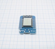
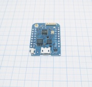
| 12 E/F | 4MB | CH340* read more here | 0, 1, 2, 3, 4, 5, 9, 12, 13, 14, 15, 16, A0 (with Voltage divider) | 1&3 (serial) | RT9013 | 5 VDC (+/-0,5V) | onboard PCB | 34.2mm x 25.6mm x ?mm | |
| 12 E/F | 16MB | CP2104 | 0, 1, 2, 3, 4, 5, 9, 12, 13, 14, 15, 16, A0 (with Voltage divider) | 1&3 (serial) | RT9013 | 5 VDC (+/-0,5V) | onboard ceramic/pigtail connector | 34.2mm x 25.6mm x ?mm | |
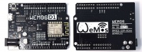
| WeMos D1 R2
|
12 E/F | 4MB | CP340G | 0, 1, 2, 3, 4, 5, 9, 12, 13, 14, 15, 16, A0 (with Voltage divider) | 1&3 (serial) | 9-24VDC Switching power supply to 5 VDC(@1A) and RT9013 | 9-24VDC (power jack), 5VDC (5V pin) | onboard PCB | 68.6mm x 53.4mm x ?mm (=Arduino UNO) |
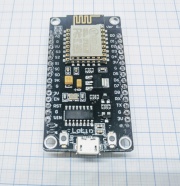
| 12 E | 4MB | CP2102 | 0, 1, 2, 3, 4, 5, 9, 12, 13, 14, 15, 16, A0 (with Voltage divider) | 1&3 (serial) | AMS1117 | 5 VDC (+/-0,5V) | onboard PCB | ?mm x ?mm x ?mm | |
| 12 E | 4MB | CP340 | 0, 1, 2, 3, 4, 5, 9, 12, 13, 14, 15, 16, A0 (with Voltage divider) | 1&3 (serial) | AMS1117 | 5 VDC (+/-0,5V) | onboard PCB | ?mm x ?mm x ?mm | |
| generic ESP8266 | 1MB | - | 0, 2 | 1&3 (serial) | Attention! ESP-01 with PUYA flash chip need to be flashed with file labeled "PUYA". | 3.3 VDC | onboard PCB | 11mm x 10mm x 2mm | |
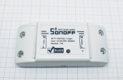
| generic ESP8266 or ESP8285 | 1MB | None | 1, 3, (14) | 0 (button), 12 (Relay 10A@230VAC), 13 (LED) | on board mains AC to 5DVC + ? 3.3V Voltage Regulator Attention! The DC power is NOT galvanically decoupled from AC power! |
90-250VAC | onboard PCB | 88mm x 38mm x 23mm | |
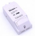
| Sonoff TH10/TH16
|
generic ESP8266 or ESP8285 | 1MB | None | 1, 3, (14) | 0 (button), 12 (Relay 10A/16A@230VAC), 13 (LED), 14 (AM2301) | on board mains AC to 5DVC + ? 3.3V Voltage Regulator Attention! The DC power is NOT galvanically decoupled from AC power! |
90-250VAC | onboard PCB | 88mm x 38mm x 23mm |
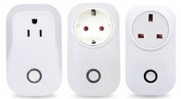
| Sonoff S20
|
generic ESP8266 or ESP8285 | 1MB | None | 1, 3, (14) | 0 (button), 12 (Relay 10A@230VAC), 13 (LED) | on board mains AC to 5DVC + ? 3.3V Voltage Regulator | 90-250VAC | onboard PCB | ? |
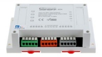
| Sonoff 4ch
|
generic ESP8285 | 1MB | None | 2, (7, 8) | 0, 9, 10, 14 (Buttons), 4 , 5, 12, 15 (Relay 10A@230VAC), 13 (LED blue) | on board mains AC to 5DVC buck converter + 3.3V Voltage Regulator | 90-250VAC | onboard PCB | 145mm x 90mm x 41mm |
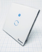
| generic ESP8285 | 1MB | None | - | 0 (button), 12 (Relay 2A@230VAC), 13 (LED blue) | on board mains AC to 5DVC buck converter + 3.3V Voltage Regulator | 90-250VAC | onboard PCB | 86mm x 86mm x 37mm (EU) 120mm x 78mm x 41mm (US) | |
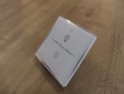
| generic ESP8285 | 1MB | None | - | 0+9 (buttons), 12+5 (Relays), 13 (LED blue) | - | 250VAC | onboard PCB | 86mm x 86mm x 37mm (EU) | |
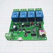
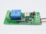
| generic ESP8285 | 1MB | None | 0, 9, 10, 14 | 4 , 5, 12, 15 (Relay 10A@230VAC), 13 (LED red) | powered by 7-32V or USB (5V) | 90-250VAC | onboard ceramic | 75mm x 75mm x 18mm | |
| generic ESP8285 | 1MB | None | - | 12 (Relay 10A@230VAC), 13 (LED red) | powered by 5V or USB (5V) | 90-250VAC | onboard ceramic | 30mm x 70mm x 18mm | |
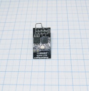
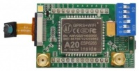
| Ai-Thinker A20 Breakout
|
generic ESP8285 | 1MB | None | ? | ? | ? | ? | SMA Connector | ? |
| ESP8266 IOT Internet Things Development Board | generic ESP8266 | 4MB | CP2104 | A0, 0, 1, 2, 3, 9, 12, 13, 14, 15, 16 (D0) needs to be high to pull reset UP. | 4&5 (OLED SSD1306 I2C display, needs 'testing' firmware for 128x32 support) | powered by USB (5V) or with battery (circuit to control 1-cell LiPo batery charging chip, likely S-8261ABPMD-G3PT2x) | 3.3-7VDC | onboard PCB | 50mm x 18mm x ?mm |

Flash modes
To flash a flash chip you need to send the bin file data using serial communication. There's multiple standards on how to do this communication (flash modes). Not all flash chips support all of these modes. The datasheet provided by the manufacturer is the best source to know what supports what. But here's a list of the different modes used:
| Mode | Extra information |
|---|---|
| DOUT | SPI host uses the "Dual Output Fast Read" command (3Bh). Two SPI pins are used to read flash data out. Slightly slower than DIO, because the address is written via the single MOSI data pin. |
| DIO | SPI host uses the "Dual I/O Fast Read" command (BBh). Two SPI pins are used to write the flash address part of the command, and to read flash data out. Therefore these phases need half the clock cycles compared to standard SPI. |
| QOUT | SPI host uses the "Quad Output Fast Read" command (6Bh). Four SPI pins are used to read the flash data out. Slightly slower than QIO, because the address is written via the single MOSI data pin. |
| QIO | SPI host uses the "Quad I/O Fast Read" command (EBh). Four SPI pins are used to write the flash address part of the command, and to read flash data out. Therefore these phases need a quarter the clock cycles compared to standard SPI. |
In terms of performance: QIO > QOUT >> DIO > DOUT. QOUT or QIO are much faster than DIO or DOUT. ESP Easy official builds uses DIO for everything except DOUT for the smaller (1M size) units.
Power for your ESP
Power supplies and USB cables are more important for the reliability of ESP Easy than you might think.
Power Supplies
Do yourself a big favor: avoid cheap power supplies! We have seen some strange behavior from cheap power supplies. If you put a voltmeter on these it shows the correct voltage. Everything looks nice. If you use an oscilloscope you may get some nasty surprises. Oscillating voltage, ripples.....
Use a high quality power supply like MeanWell or similiar. It should have at least a current of 1..2 ampere.
USB Cables
If you are using a nodeMCU, a WeMos or another USB-powered module, be aware of using good quality USB cables. Cheap cables use really thin wires. For transfering data and some milliampere of current these are ok. For an ESP module they possibly are too weak. Voltage drops and some warm boot occurs.
As a rule of thumb: Use USB cables as thick and as short as possible. If you receive warm boots for no obvious reason try a capacitor of at least 470µF from 3.3V to ground as near to the module as possible.
A good power supply is recommended anyways as USB power from the computer is always limited. Do not use the micro USB port for anything but flashing and lab tests. Use Vin instead (on WeMos D1 mini the port is simply labeled "5V").
Checking Voltage
If you need to check voltage the first step is a good quality voltmeter or multimeter. Whereever possible put the probes directly on the ESP-pins of the nodeMCU or WeMos module.
Please be aware that a digital voltmeter is slow. The result you see on the display is always an average value. If you really need to know what's going on with your power supply an oscilloscope is necessary as it can cope with short voltage peaks or drops.